Multimeters UNI-T
All Multimeters Advanced filters → |
Popular modelsCompare using chart →
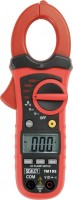
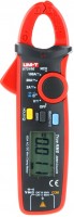
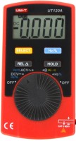
clamp meter, fast. voltage: 200 mV, 600 V, aC voltage: 200 mV, 600 V, aC current: 400 A, resistance: 200 Ω, 20 MΩ, autorange
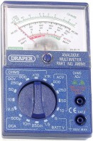
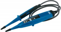
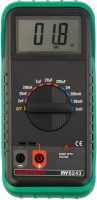
multimeter, analogue, fast. voltage: 500 V, aC voltage: 500 V, fast. current: 10 A, resistance: 10 Ω
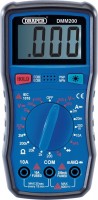
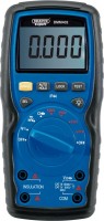
multimeter, fast. voltage: 200 mV, 600 V, aC voltage: 600 V, fast. current: 2000 µA, 10 A, resistance: 200 Ω, 2 MΩ, transistor test
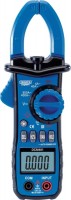
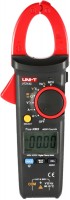
clamp meter, fast. voltage: 400 mV, 600 V, aC voltage: 400 mV, 600 V, aC current: 600 A, resistance: 400 Ω, 40 MΩ, autorange
insulation tester (megaohmmeter), fast. voltage: 400 mV, 1000 V, aC voltage: 400 mV, 1000 V, resistance: 400 Ω, 40 MΩ, autorange
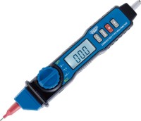
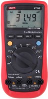
multimeter, fast. voltage: 200 mV, 600 V, aC voltage: 2000 mV, 600 V, fast. current: 0.2 A, aC current: 0.2 A, resistance: 200 Ω, 20 MΩ, autorange, NCV
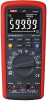
clamp meter, fast. voltage: 200 mV, 600 V, aC voltage: 2000 mV, 600 V, fast. current: 100 A, aC current: 100 A, resistance: 200 Ω, 20 MΩ, autorange, true RMS, NCV
multimeter, fast. voltage: 600 mV, 1000 V, aC voltage: 600 mV, 750 V, fast. current: 600 µA, 10 A, aC current: 600 µA, 10 A, resistance: 600 Ω, 60 MΩ, autorange, true RMS, NCV
multimeter, fast. voltage: 4000 mV, 600 V, aC voltage: 4000 mV, 600 V, resistance: 400 Ω, 40 MΩ, autorange
multimeter, fast. voltage: 220 mV, 1000 V, aC voltage: 220 mV, 750 V, fast. current: 200 µA, 10 A, aC current: 200 µA, 10 A, resistance: 220 Ω, 220 MΩ, autorange, true RMS
clamp meter, fast. voltage: 400 mV, 600 V, aC voltage: 4000 mV, 600 V, fast. current: 400 A, aC current: 400 A, resistance: 400 Ω, 40 MΩ, autorange, true RMS, NCV
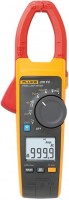
clamp meter, fast. voltage: 500 mV, 1000 V, aC voltage: 1000 V, fast. current: 999 A, aC current: 2500 A, resistance: 0.06 MΩ, true RMS
You might be interested in
Multimeters: specifications, types
Show all
Product type
— Voltmeter. Electrical voltage is measured in volts; accordingly, devices of this type are designed primarily to measure voltage, and most often - only for this and nothing more. However, in addition to voltage, in practice one often has to deal with many other parameters, and modern technologies make it possible to create compact, functional and at the same time inexpensive universal devices. Therefore, voltmeters in their pure form are found and used relatively rarely, and most users dealing with electrical engineering prefer to use multimeters (see below).
— Multimeter. Devices of this type are also colloquially called "testers". A multimeter is a multi-purpose measuring instrument that combines the functions of at least a voltmeter, ammeter and ohmmeter - that is, it can measure voltage, power and resistance. In addition, other functions may be provided - for example, measuring capacitance, inductance, temperature (see “Functions”). For measurements, as a rule, a pair of probes is used. Due to their versatility combined with a relatively low cost, multimeters are the most popular type of measuring instruments; they can be used both for simple tasks such as checking radio components or household networks, and for working with complex circuits.
— Current clamps. Initially, such clamps are specific devices that allow you to measure power strength in...a non-contact manner, without touching the wires or interfering with the operation of the circuit. They operate as follows: the clamps cover the wire and, due to the characteristics of the magnetic field around it, measure the power strength. Both AC and DC power can be measured this way (though specific capabilities will, of course, vary by model). In addition to measurements without breaking the circuit, the advantage of clamps is the ability to work with high currents and voltages - hundreds of amperes in networks of hundreds of volts; Moreover, the measurements themselves are safer than with the usual contact method. On the other hand, the measurement accuracy is relatively low - usually no higher than class 2.5. In addition, the reliability of the result strongly depends on the correct position of the clamps, and with alternating power, also on the uniformity of the sinusoid (however, in advanced models special circuits may be provided to compensate for this dependence). In addition, non-contact measurement is not always practically applicable. Current clamp meters can be made in the form of a specialized device, but most often devices of this type are made in the form of multimeters, supplemented with a magnetic circuit for non-contact measurements and also capable of working using the usual contact method.
- Oscilloscope. Oscilloscopes are instruments designed to observe, measure and record electrical signal parameters. A distinctive feature of a classic oscilloscope is the screen on which the device builds a graph of the signal supplied to the input. Simultaneous operation with several signals can be supported (for more details, see “Number of channels”). However, some models do not have their own screen and are connected to a computer for measurements (see “USB oscilloscope”). Many signal parameters can be determined from its graph - this graph is usually supplemented by a coordinate scale that clearly illustrates frequency, amplitude, etc.; however, the oscilloscope can also display some parameters, such as phase angle, as specific numerical data. Modern oscilloscopes are capable of operating with frequencies up to gigahertz inclusive and most often use digital circuits (see “Type”), which makes them superior in accuracy to classic analog instruments.
- Skopmeter. Universal devices that combine both a multimeter and an oscilloscope in one housing. Both of these types are described in more detail above; Let us note here that such a combination provides very extensive functionality, however, scope meters are not cheap, and their measurement accuracy is lower than that of specialized multimeters and/or oscilloscopes.
— Insulation tester (megaohmmeter). Instruments that can be used to check the quality of insulation. For such a test, it is enough to determine the electrical resistance of the insulation - however, it can be very high, millions of ohms or even more. In light of this, the traditional measurement method - applying a low voltage to the material, determining the strength of the resulting power and calculating the resistance - is not suitable for insulation; special procedures are needed. Devices that provide such capabilities are called megohmmeters. They can support different insulation testing techniques; These methods are described in detail in special sources, and the features of specific devices are described in the manufacturer’s documentation. We only note that modern devices from this category are rarely made in the form of highly specialized devices - most often these are the same universal multimeters, supplemented with an insulation testing mode.
— Voltage tester. Portable pen-shaped testers for safely measuring voltage in an outlet or indicating the presence of power in wiring. The latter detect voltage in a non-contact manner, i.e. without having to touch the object. With their help, you can check the functionality of the outlet, detect the break point of the laid wiring or the point where the wire is broken. The voltage is determined by the tester at a distance of several centimeters, thereby preventing electric shock and other unpleasant consequences. Voltage meters usually operate on two “little finger” batteries (AAA type).
Type
The basic principle on which the measuring instrument works.
— Digital. A distinctive external feature of such devices is that a display is used to display the measurement results (oscilloscopes that have a display by definition can technically be analogue, but such devices are practically not used today). Digital models work as follows: the measured parameter is processed by special electronic circuits that convert the measurement results into a digital signal and display the data obtained in the form of numbers or graphs. Most modern multimeters and other measuring instruments use this principle of operation: it provides high measurement accuracy and ease of reading, allows you to work with different parameters and numerous additional functions. At the same time, the devices themselves are light, compact, and thanks to the current level of technology, they are also inexpensive. The disadvantage of this option can be called the fact that power sources are required for operation — usually batteries or accumulators; and without power, the device becomes useless. Also note that in digital oscilloscopes, the circuitry of the device itself can introduce distortions into the final signal pattern; therefore, such devices are considered poorly suited for measurements where high accuracy and reliability are a key requirement.
— Analogue. Historically — the first principle used in electrical measuring instruments. Measurement in su...ch devices is carried out due to the fact that an electric current or signal directly affects the indicator element. For example, when measuring current with an analogue ammeter, the current passes through a spring-loaded coil with an arrow installed between two magnets, and the higher the current, the further the arrow deviates on the scale. In oscilloscopes, everything is somewhat more complicated, but even there the basic principle of operation is similar, and the role of the arrow is played by a beam in a cathode ray tube that forms an image on the screen (according to the same principle as in a CRT TV). The advantages of analogue instruments compared to digital ones are the simplicity of design, somewhat lower cost, and the ability to make some measurements (at least in the ammeter and voltmeter mode) without power sources. In addition, analogue oscilloscopes do not have additional converters and other potential sources of noise and distortion, so this option is considered optimal for high-precision measurements. At the same time, in multimeters, the accuracy of measurements, on the contrary, is low (both due to the inaccuracy of the arrows and due to errors in reading the readings from the scales). In addition, in all analogue instruments, the range of available functions is not as extensive as in digital ones, and scales often have to be equipped with multi-level markings, which complicate the quick reading of data. As a result, this principle of operation is rare today, and mainly among low-cost models.
Form factor
- Tweezers. Multimeters with probes in the form of tweezers, the sponges of which are in direct contact with the contacts of the elements on the board. Devices of this order are suitable for measuring the electrical parameters of SMD components and other miniature surface mount elements.
- Pen. Models of this type have a compact handle design with a built-in “red” probe and electronics. The second probe in their design is placed on the tip of the wire. The main strong point of multimeters in the pen form factor is the convenience of measurements on weight or under the ceiling, where it is inconvenient to hold the device with both hands.
- Pen. Models of this type have a compact handle design with a built-in “red” probe and electronics. The second probe in their design is placed on the tip of the wire. The main strong point of multimeters in the pen form factor is the convenience of measurements on weight or under the ceiling, where it is inconvenient to hold the device with both hands.
Measurements
The parameters that the device can measure.
— Tension. Voltage (potential difference between two points in a circuit), measured in volts. One of the basic electrical parameters, supported by all types of devices, except for oscilloscopes (see "Device"). Parallel connection is used for measurement. In analogue instruments (see "Type") voltage measurement can be carried out without power.
— Current. The strength of the current flowing through a certain section of the circuit; measured in amperes. There are two ways to measure current strength: traditional and non-contact. The first one is available in almost all devices with the ammeter function, for this it is necessary to open the circuit and connect the device to the gap in series (moreover, with the analogue principle of operation, the ammeter does not require power). The second method is used in current clamps (see "Device"). In most cases, the models are able to measure direct and alternating current.
— Impedance. Impedance of a certain element to direct electric current; measured in ohms. Note that in this case we are talking about traditional measurements that are not associated with ultra-high resistances characteristic of insulation (in insulation, this parameter is checked using a separate method, see more about it below...). Impedance measurements are carried out as follows: a certain voltage (low, within a few volts) is applied to the probes of the device, after which they are applied to the place of measurement — and the impedance of the tested section of the circuit or other object is calculated from the strength of the current flowing through the formed circuit. Thus, to operate in ohmmeter mode, a power source is required — even for an analogue instrument.
— Capacity. The capacitance of a capacitor is measured in farads (usually microfarads and other derived units). The measurement itself is carried out by supplying an alternating current to the capacitor. This function can be useful both for clarifying the capacitance of unmarked capacitors (initially unmarked or with erased inscriptions), and for checking the quality of signed parts. On capacitors, in addition to the nominal capacity, the maximum deviation from the nominal value may be indicated; if the measurement results are outside the tolerance limits, then it is better not to use the part. If the deviation is not indicated, then it can be assumed that it should be less than 10% of the nominal value. For example, for a 0.5 uF part, the range of allowable capacitances will be 0.45 – 0.55 uF.
— Temperature. Temperature measurement — usually, using an external remote sensor, usually on a probe. In electrical engineering, this function is used to control the operation of parts that are sensitive to overheating or that must operate in a certain temperature regime.
— Frequency. The ability to measure the frequency of an electrical signal is primarily characteristic of oscilloscopes and scopometers, but it can also be found in other types of devices — the same multimeters (see "Device"). This, usually, implies the ability to display specific numbers corresponding to the frequency in hertz.
— Duty cycle. Duty cycle is one of the basic characteristics of a uniform pulse signal, namely the ratio of its repetition period to the duration of a single pulse. For example, if each 2 ms pulse is followed by a 6 ms pause, then the signal repetition period will be T = 6 + 2 = 8 ms, and the duty cycle will be S = 8/2 = 4. Do not confuse the duty cycle with the duty cycle: although these characteristics describe the same property of the signal, they do it in different ways. The duty cycle is the reciprocal of the duty cycle, the ratio of the pulse length to the repetition period (in our example, it will be equal to 2/8 = 25%). This term is found mainly in English and translated sources, while in east european electrical engineering the term "duty cycle" is adopted.
— Inductance. Inductance is the main operating parameter of any inductor. The ability to measure this parameter is important in light of the fact that specialists and radio amateurs often make coils on their own, and it is extremely difficult, if not impossible, to determine the characteristics of a part without a special device. The principle of measuring inductance is similar to determining the capacitance of a capacitor (see above) — passing an alternating current through the coil and tracking its "response". However, this function is much less common than capacitance measurement.
— Insulation impedance. Insulation impedance of electrical wires to alternating current. Insulation, by definition, has an extremely high impedance, so the traditional way of measuring impedance (at low operating voltage, see above) is not applicable here — the currents would be too weak and it would be impossible to measure them accurately. Therefore, to check insulating materials and other dielectrics, not ohmmeters are used, but special devices — megaohmmeters (or multimeters that support this mode). A distinctive feature of the megohmmeter is a high operating voltage — hundreds or even thousands of volts. For example, to test insulation with an operating voltage of 500 V, the same megger voltage is required, for a 3000 V material, a 1000 V device, etc., the requirements for different types of insulation are described in more detail in special sources. To achieve this voltage, an external high-voltage module may be required, however, many multimeters that support this type of measurement are also capable of independently generating short-term high-voltage pulses from low-voltage power supplies such as AA batteries or PP3 (see "Battery type"). Note that when working with a megohmmeter, you must carefully follow the safety rules — due to the high operating voltage.
— Power. The power of the electric current is determined by two basic parameters — current strength and voltage; roughly speaking, volts must be multiplied by amps, the result obtained will be the power in watts. Thus, theoretically, this parameter can be determined without a special function for measuring power — it is enough to determine the voltage and current strength. However, some measuring instruments have a special mode that allows you to immediately measure both basic parameters and automatically calculate the power based on them — this is more convenient and faster than doing calculations separately. Many of these devices belong to current clamps (see "Device") and the measurement of the current strength when determining the power is carried out in a non-contact way, and the voltage is measured by the classic contact method. There are other design options — for example, an adapter for a socket: an electrical appliance is connected to a socket through such an adapter, and a multimeter takes current and voltage data from the adapter. We also recall that the active (useful) power of the alternating current is not always equal to the full one — with a capacitive and/or inductive load, part of the power (reactive power) is “consumed” by capacitors / coils. You can read more about these parameters in special sources, but here we note that different models of multimeters may have different capabilities for measuring different types of power; These points do not hurt to clarify before buying in advance.
— Phase angle. Measurement of the degree of shift of two electrical signals (or signal parameters) in phase. Specific types and features of such measurements are different, the most popular are two options. The first is to measure the difference between the phases of a three-phase power supply, primarily to assess its overall quality. The second is an assessment of the phase shift between current and voltage that occurs with a reactive (capacitive or inductive) load on an alternating current source; the ratio between active and apparent power (power factor, "cosine phi") directly depends on such a shift.
— Rotation frequency. In this case, most often we are talking about the possibility of measuring the speed of the internal combustion engine. Accordingly, such models usually refer to specialized automotive multimeters. They are designed mainly for diagnostics and testing of engines that do not have electronic ignition systems. To measure, usually, you need to set the multimeter to the number of engine cylinders and connect it to the ignition system (the specific connection method must be specified in the documentation for the car).
Note that this list does not list all, but only the most popular measurements found in modern multimeters and other devices of a similar purpose. In addition to them, the design may provide more specific features — see "Other Dimensions" for more details.
Other measurements
Additional types of measurements provided in the device and not related to the main methods of measurement (see "Measurements"). Examples include measuring the amount of electricity consumed over a certain time, power factor (the ratio between active and apparent power, “cos phi”), non-contact voltage measurement, determining the angle of the closed state of breaker contacts in automotive ignition systems, as well as more specific parameters — like lighting or sound level in decibels.
Current type
The type of current the device is designed to measure. In this case, not all measurement modes are implied, but only the determination of the current strength, that is, operation in the ammeter mode.
— Constant. A current that has a strictly defined polarity and constantly flows in one direction, from minus to plus. Such a current is found mainly in electronic circuits behind power supplies, in compact electronics powered by batteries, as well as in car on-board networks. However, during electrical work in domestic and industrial AC networks, it is relatively rare to measure the current strength; therefore, among such devices, there are often models that are compatible with "variable" networks in terms of voltage (see below), but not compatible in terms of current. In general, there are fewer DC-only devices on the market than combined ones (see below).
— Variable. A current that changes direction several dozen times per second (for example, in 230 V household networks, the standard frequency is 50 or 60 Hz, depending on the region). Such a current is a standard for domestic and industrial networks: it is convenient in that it does not require polarity when connecting end consumers, and it also provides some features that are not available for direct current (in particular, transformers can only be used with such a power supply). However, relatively few devices are produced strictly for alternating current, combined options are more common (see below).
...
— Constant / variable. This category includes models that can measure both direct and alternating current. The features of both options are described above, and their support in one device makes it universal and allows it to be used in any type of networks and circuits — the main thing is that the current limits are observed (see below).
Voltage type
The kind of voltage with which the device is able to work — that is, which it is able to measure when working as a voltmeter.
Almost all modern devices for measuring voltage support operation in both AC and DC networks. For more details about the features of these types of current, see above; here we note that the function of a "variable" voltmeter is useful primarily when working with standard household and industrial power networks, and a "constant" one — when working with low-current circuits, battery-powered devices and on-board auto networks. Occasionally, there are models only for alternating voltage — their functionality is limited, but they are still suitable for electrical work in the mentioned stationary networks. But devices only for direct voltage are practically not produced — this makes no sense, it is more justified to provide both types of voltage in such a device.
Almost all modern devices for measuring voltage support operation in both AC and DC networks. For more details about the features of these types of current, see above; here we note that the function of a "variable" voltmeter is useful primarily when working with standard household and industrial power networks, and a "constant" one — when working with low-current circuits, battery-powered devices and on-board auto networks. Occasionally, there are models only for alternating voltage — their functionality is limited, but they are still suitable for electrical work in the mentioned stationary networks. But devices only for direct voltage are practically not produced — this makes no sense, it is more justified to provide both types of voltage in such a device.
DC voltage minimum
The upper limit of the lower sub-range in which the device can measure DC voltage (see "Type of voltage").
The operating ranges of modern multimeters and other measuring instruments are usually divided into subranges. This is done for accuracy and convenience when measuring: for example, to assess the quality of AA batteries, you can set the subrange “up to 3 V” — this will give an accuracy of up to tenths, or even hundredths of a volt, unattainable when measuring with a higher threshold. The minimum constant voltage describes exactly the lower subrange, designed to measure the smallest voltage values: for example, if 2000 mV is indicated in this paragraph, this means that the lower subrange covers values \u200b\u200bup to 2000 mV (i.e. up to 2 V).
It is worth choosing according to this indicator taking into account the specifics of the planned application: for example, a device with low rates can be useful for delicate work, such as repairing computers or mobile phones, but for servicing the on-board electrical network of a car, especially high voltage sensitivity is not required.
DC voltage max.
The highest DC voltage (see “Voltage type”) that can be effectively measured with this instrument.
Compliance with this parameter is important not only for correct measurements, but also from a safety point of view. Measuring too high voltage can lead to malfunctions of the device, ranging from the operation of emergency protection (and it can take the form of a disposable fuse that requires replacement after operation) and ending with a complete failure and even fire. Therefore, it is impossible to exceed this indicator anyway. Yes, and choosing a device for maximum voltage is worth with a certain margin — at least 10 – 15%: this will give an additional guarantee in case of emergency situations. On the other hand, the margin should not be too large: a high constant voltage threshold can degrade the accuracy of measurements at low voltage, as well as affect the price, dimensions and weight of the device.
Note that most multimeters and other similar devices have several measurement ranges, with different maximum thresholds. So, for a safe measurement of voltage close to the maximum, you need to set the appropriate mode in the settings.
Measurement accuracy (V⁻)
Measurement accuracy provided by the instrument.
Measurement accuracy for multimeters is usually indicated by the smallest error (in percent) that the device is able to provide when measuring direct current. The smaller the number in this paragraph, the higher the accuracy, respectively. At the same time, we emphasize that it is the smallest error (the highest accuracy) that is usually achieved only in a certain measurement range; in other ranges, the accuracy may be lower. For example, if in the range "1 — 10 V" the device gives a maximum deviation of 0.5%, and in the range "10 — 50 V" — 1%, then 0.5% will be indicated in the characteristics. Nevertheless, according to this indicator, it is quite possible to evaluate and compare modern multimeters. So, a device with a lower claimed error, usually, and in general will be more accurate than a model with a similar performance with a larger error.
Data on measurement accuracy in other ranges and modes can be given in the detailed characteristics of the device. However, in fact, this information is required not so often — only for certain specific tasks, where it is fundamentally necessary to know the possible error.
AC voltage minimum
The upper limit of the lower sub-range in which the device can measure AC voltage (see "Type of voltage").
The operating ranges of modern multimeters and other measuring instruments are usually divided into subranges. This is done for accuracy and convenience in measurements: for example, to test a transformer that should output 6 V, it makes sense to set a subrange with an upper threshold of 10 V. This will ensure accuracy up to tenths of a volt, unattainable when measuring with a higher threshold. The minimum constant voltage describes exactly the lower subrange, designed to measure the smallest voltage values: for example, if 2000 mV is indicated in this paragraph, this means that the lower subrange covers values \u200b\u200bup to 2000 mV (i.e. up to 2 V).
If the device is purchased for measurements in stationary networks — household at 230 V or industrial at 400 V — you can ignore this parameter: usually, the minimum subranges are not used. But to work with power supplies, step-down transformers and various “thin” electronics served by low voltage alternating current, it makes sense to choose a model with a lower minimum voltage. This is connected not only with the measurement range: a low threshold, usually, indicates a good measurement accuracy at low voltages in general.
AC voltage max.
The largest alternating voltage (see “Type of voltage”) that can be effectively measured using this model. This parameter is important not only for measurements as such, but also for safe handling of the device: measuring too high voltage will, at best, trigger emergency protection (and it is possible that after that you will have to look for a new fuse to replace the burned one), at worst — to equipment failure or even fire. In addition, for safe measurements, a voltage margin is highly desirable — this is due both to the characteristics of the alternating current and to the possibility of various emergency situations in the network, primarily voltage surges. For example, for 230 V networks, it is desirable to have a device for at least 250 V, and preferably 300 – 310 V; detailed recommendations for other cases can be found in special sources.
Note that most multimeters and other similar devices have several measurement ranges, with different maximum thresholds. So, for a safe measurement of voltage close to the maximum, you need to set the appropriate mode in the settings.
Note that most multimeters and other similar devices have several measurement ranges, with different maximum thresholds. So, for a safe measurement of voltage close to the maximum, you need to set the appropriate mode in the settings.
DC minimum
The upper limit of the lower sub-range in which the device can measure direct current (see "Type of current").
The operating ranges of modern multimeters and other measuring instruments are usually divided into subranges. This is done for accuracy and convenience in measurements: the lower the subrange, the smaller values it covers, the higher the measurement accuracy at low current values. The minimum direct current describes exactly the lower range, designed for the weakest current values: for example, if the characteristics in this paragraph indicate 500 μA, this means that the lower subrange allows you to measure currents from 0 to 500 μA.
It is worth choosing according to this indicator taking into account the specifics of the planned application: for example, a device with low rates can be useful for delicate work, such as repairing computers or mobile phones, but for servicing the on-board electrical network of cars, especially old ones, especially high current sensitivity is not required.
DC max.
The highest direct current (see “Type of current”) that the device is able to measure without overloads and related troubles (such as “flying” fuses or even failure).
When choosing for this parameter, it is worth remembering that even at relatively low voltages, the currents can be quite high if the power source provides the appropriate power — for example, a 12 V car battery is quite capable of delivering currents of hundreds of amperes. Actually, compatibility with high direct currents is important primarily for automotive devices; however, the matter is not limited to this.
For safe use, it is desirable to have a certain margin for maximum current. Also, do not forget that before measurements you need to set the appropriate settings.
AC minimum
The upper limit of the lower sub-range in which the device can measure alternating current (see "Type of current").
The operating ranges of modern multimeters and other measuring instruments are usually divided into subranges. This is done for accuracy and convenience in measurements: the lower the subrange, the smaller values it covers, the higher the measurement accuracy at low current values. The minimum alternating current describes exactly the lower range, designed for the weakest current values: for example, if the characteristics in this paragraph indicate 500 μA, this means that the lower subrange allows you to measure currents from 0 to 500 μA.
It is worth choosing according to this indicator taking into account the specifics of the planned application: for example, a device with low rates can be useful for delicate work, such as repairing computers or mobile phones, but especially high current sensitivity is not required for servicing household electrical networks.
AC max.
The largest alternating current (see "Type of current") that can be measured with this device. In no case should this parameter be exceeded — otherwise various troubles are possible, from the operation of the device's emergency protection (with further replacement of fuses) to fire.
When choosing for this parameter, it is worth remembering that even at relatively low voltages, the currents can be quite high if the power supply provides adequate power. For safe use, it is desirable to have a certain margin for maximum current. Also, do not forget that before measurements you need to set the appropriate settings.
When choosing for this parameter, it is worth remembering that even at relatively low voltages, the currents can be quite high if the power supply provides adequate power. For safe use, it is desirable to have a certain margin for maximum current. Also, do not forget that before measurements you need to set the appropriate settings.
Impedance minimum
The upper limit of the lower sub-range in which the device can measure resistance.
The operating ranges of modern multimeters and other measuring instruments are usually divided into subranges. This is done for accuracy and convenience in measurements: the lower the subrange, the smaller the values it covers, the higher the accuracy of measurements at low resistance values. The minimum resistance describes exactly the lower range, designed for the weakest current values: for example, if the characteristics in this paragraph indicate 500 Ohms, this means that the lower subrange allows you to measure resistance from 0 to 500 Ohms.
When choosing for this indicator, you need to consider how important it is for you to accurately measure small resistances. At the same time, we note that the 500 Ohms given in the example are a fairly good indicator, indicating a fairly solid resistance measurement accuracy; in relatively inexpensive multimeters, this indicator can be 2.5 or even 10 kΩ, which ensures accuracy at best up to several tens of ohms.
Impedance max.
The highest resistance that the instrument can effectively measure.
When choosing according to this indicator, you must first take into account the largest resistances that are supposed to be measured. And if we are talking about an analogue device (see "Type"), you must also remember that as you approach the maximum resistance, the measurement accuracy drops sharply. This is due to the peculiarities of measuring and grading the scale in such devices: for example, with a maximum resistance of 1 MΩ, the division value in the range of 0 – 2 kΩ can be 0.2 kΩ, in the range of 2 – 6 kΩ — 0.5 kΩ, in the range of 6 – 10 kOhm — already 1 kOhm, and closer to the maximum this figure can reach tens and even hundreds of kilo-ohms. Therefore, it is worth choosing an analogue device in such a way that its maximum resistance is at least 10 times higher than the largest resistances that are planned to be measured — only under this condition is a more or less acceptable measurement accuracy ensured.
When choosing according to this indicator, you must first take into account the largest resistances that are supposed to be measured. And if we are talking about an analogue device (see "Type"), you must also remember that as you approach the maximum resistance, the measurement accuracy drops sharply. This is due to the peculiarities of measuring and grading the scale in such devices: for example, with a maximum resistance of 1 MΩ, the division value in the range of 0 – 2 kΩ can be 0.2 kΩ, in the range of 2 – 6 kΩ — 0.5 kΩ, in the range of 6 – 10 kOhm — already 1 kOhm, and closer to the maximum this figure can reach tens and even hundreds of kilo-ohms. Therefore, it is worth choosing an analogue device in such a way that its maximum resistance is at least 10 times higher than the largest resistances that are planned to be measured — only under this condition is a more or less acceptable measurement accuracy ensured.
Clamp opening size
The distance that the tips of the jaws of the measuring instrument can open relative to each other. Relevant for current clamp metres.
Max. conductor size
The diameter of the conductor in millimetres, on which the electrical parameters can be measured with a clamp metre.
Display size
The diagonal of the display used in the instrument.
Digital models are equipped with displays (see "Type"), and for an oscilloscope, this item of equipment is mandatory regardless of type. Actually, the diagonal of the display is important primarily for oscilloscopes and scopmeters (see "Device"): the larger the display, the more accurate and convenient for perception the signal graph displayed on it and other parameters. On the other hand, a screen that is too large will cost a lot, and will also significantly affect the overall dimensions of the entire device. Therefore, the best compromise for such devices is considered to be a diagonal of 5 – 6 "— it allows you to get quite clear data and at the same time does not lead to a significant increase in the price and dimensions of the device.
For classic multimeters, the display size is not so critical, besides, manufacturers try to select the screen in such a way that it is not too large and at the same time convenient enough to read the readings. Therefore, in such cases, the screen size may not be indicated at all.
Display count
The highest number that the DMM display can display (see "Type").
This indicator determines the range in which measurements can be taken without changing the settings. So, if the maximum number is 1999, then the measurement can be made in the range from 0 to 1999 of the selected units of measure — for example, from 0 to 1999 V if volts are selected, from 9 to 1999 mA (1.999 A) if milliamps are selected, etc. At the same time, 1999 and less for modern measuring instruments are considered a rather modest indicator, from 2000 to 3999 — average, 4000 – 9999 — not bad, and in the most advanced models this number exceeds 10000.
Note that the maximum displayed number is directly related to the display capacity — see below.
Display value
The digit capacity of the display installed in the digital instrument (see "Type").
Bit depth is the number of characters that can be displayed on the screen at the same time. The maximum displayed number directly depends on it (see above): for example, if the digit capacity is 4, then the device has a display for 4 full digits and is able to display a number up to 9999 inclusive. However, there are also more specific markings — with a fraction, for example, 3 1/2 or 4 3/4. This means that the largest (left) digit in this model is incomplete and the maximum digit that it can display is less than 9. Specifically, such marking is deciphered as follows: an integer means the number of full digits, the numerator of a fraction is the maximum number displayed in an incomplete digit, the denominator is the total number of values supported by an incomplete digit. Considering the above examples, 3 1/2 means a four-digit display with the maximum number in 1999: three full digits with a maximum value of 9, plus one partial digit with a maximum value of 1 and two options (1 and 0). Similarly, 4 3/4 corresponds to the maximum number 39999, with 4 options for values in the partial digit (0, 1, 2, 3).
Bit depth is the number of characters that can be displayed on the screen at the same time. The maximum displayed number directly depends on it (see above): for example, if the digit capacity is 4, then the device has a display for 4 full digits and is able to display a number up to 9999 inclusive. However, there are also more specific markings — with a fraction, for example, 3 1/2 or 4 3/4. This means that the largest (left) digit in this model is incomplete and the maximum digit that it can display is less than 9. Specifically, such marking is deciphered as follows: an integer means the number of full digits, the numerator of a fraction is the maximum number displayed in an incomplete digit, the denominator is the total number of values supported by an incomplete digit. Considering the above examples, 3 1/2 means a four-digit display with the maximum number in 1999: three full digits with a maximum value of 9, plus one partial digit with a maximum value of 1 and two options (1 and 0). Similarly, 4 3/4 corresponds to the maximum number 39999, with 4 options for values in the partial digit (0, 1, 2, 3).
Number of channels
The number of channels supported by the oscilloscope or scopmeter (see "Device"). In fact, this is the maximum number of individual signals that the device can process simultaneously.
Support for multiple channels allows you to compare several electrical signals on the oscilloscope in real time — superimposing graphs built by the device on top of each other can give a specialist a lot of useful information.
Support for multiple channels allows you to compare several electrical signals on the oscilloscope in real time — superimposing graphs built by the device on top of each other can give a specialist a lot of useful information.
Bandwidth
Bandwidth of an oscilloscope or scopmeter (see “Device”).
This parameter characterizes the frequencies that the device can process, more precisely, the maximum frequency values. However, the bandwidth is a rather tricky indicator: this parameter does not indicate the maximum allowable signal frequency, but the frequency at which the data on the amplitude of the sinusoidal signal received by the device are 3 dB lower than the actual amplitude. If we translate this indicator into percentages, then the error of such a measurement will reach 30% — for high-quality measurements this is unacceptably high. Therefore, the selection rule for this indicator is as follows: the bandwidth of the oscilloscope must be at least 3 times the maximum frequency of the signal that is supposed to be measured. Only in this case it is possible to achieve more or less accurate results (with an error of less than 5%). And ideally, the bandwidth should be 5 times or more — this will provide an error of only 3% or less.
This parameter characterizes the frequencies that the device can process, more precisely, the maximum frequency values. However, the bandwidth is a rather tricky indicator: this parameter does not indicate the maximum allowable signal frequency, but the frequency at which the data on the amplitude of the sinusoidal signal received by the device are 3 dB lower than the actual amplitude. If we translate this indicator into percentages, then the error of such a measurement will reach 30% — for high-quality measurements this is unacceptably high. Therefore, the selection rule for this indicator is as follows: the bandwidth of the oscilloscope must be at least 3 times the maximum frequency of the signal that is supposed to be measured. Only in this case it is possible to achieve more or less accurate results (with an error of less than 5%). And ideally, the bandwidth should be 5 times or more — this will provide an error of only 3% or less.
Sample rate
The sampling rate provided by an oscilloscope or scopmeter (see "Device") with digital operation (see "Type").
When digitizing, the incoming signal is decomposed into separate fragments, for each of which the level is measured. In other words, a sinusoid or a similar smooth line is decomposed into separate "steps", and the digital signal is a set of data about each particular "step". The sampling rate describes how many such “steps” there are in one second of the signal; for example, 1 GS/s corresponds to 1 billion steps per second.
Without going into mathematical details, we can say that for high-quality signal processing, the sampling frequency should be at least 4 to 5 times higher than the bandwidth (see above). This is due to the peculiarities of digital processing of high-frequency signals, including rectangular.
Functions
- Checking the transistor. The ability to use the device to test transistors, more precisely, the presence of an appropriate mode in the design of the device. Technically, the performance of a transistor can be checked to a certain extent with an ordinary ohmmeter, for this there is an appropriate technique. Nevertheless, it is much easier to use a special mode - just connect the transistor to the multimeter in an appropriate way, and the device will automatically give data on the health or malfunction of the part (and sometimes additional characteristics for it). Most often, for such measurements, there is a special block on the case with a set of sockets for transistor outputs (with separate sets of sockets for pnp and npn types).
- Checking the diode. The presence of a special diode test mode in the design of the multimeter. The principle of a diode is to allow electric power to flow in only one direction; therefore, the serviceability of such a part itself can be determined without a special mode, for example, in the mode of a conventional ohmmeter, “continuity” of the circuit (see below), or in some other ways. However, special mode is often more convenient - both due to the simplicity of the procedure itself, and due to the fact that many devices in this mode are also able to measure the forward voltage drop across the diode (the lowest voltage required to pass power in the forward direction...).
— "Continuity" of the chain. Possibility of operation of the device in the "continuity" mode of the circuit - checking the presence of contact between two selected points. This mode differs from the usual check with an ohmmeter in that the presence of a contact is accompanied by an audible signal (hence the name). Such a signal saves the user from having to look at the scale of the device every time to clarify the presence or absence of contact, and this greatly speeds up the work and can be very useful if you need to “ring out” many sections at once.
- Meander generator. Ability to operate the device in the meander generation mode - a signal with a rectangular pulse shape and a duty cycle (see above) at level 2. The graph of such a signal looks like a set of rectangular peaks and dips of the same length. Meander is a regular signal format for modern digital technology; a signal of this type, generated by a multimeter, is used to test microcircuits, logic elements, amplifiers and other similar elements and circuits (for performance, signal flow, etc.).
— Non-contact detection (NCV). Ability to detect live parts without direct contact with them. This method of detection is as safe as possible, besides, it allows you to find elements hidden from the eye: for example, using a device with this function, you can detect wiring in walls and determine places where you can drill without fear of damaging the wire.
— True RMS. Ability to measure with the True RMS device - the true RMS value of the strength of the alternating power (see "Type of power"). The strength of the alternating power is determined not by the actual value (it will be different at each moment of time), and not by the maximum amplitude (after all, the maximum values also occur only at certain points in time), but by the root mean square. At the same time, in devices that do not support True RMS, this value is displayed as follows: the alternating power is rectified, its value is determined and multiplied by a factor of 1.1 (this is due to the mathematical features of the measurements). However, this method is only suitable for an ideal sinusoid; with a distorted signal, it gives a noticeable, and often even unacceptably high error. Distortions are found in almost any AC network, which can lead to serious measurement errors and subsequent problems (for example, to the selection of too “weak” automatic fuse). True RMS technology takes into account all these features: devices bearing this marking are able to accurately measure AC RMS power, regardless of how its shape corresponds to a perfect sine wave.
- Auto-selection of the measuring range. A function that allows the device to automatically select the optimal measurement range - so that the result is displayed on the screen as accurately as possible. This function is found only in digital instruments (see "Type"). Note that when using it, the user will still have to set certain basic settings - for example, “direct power, power, milliamps” or “alternating power, voltage, volts”. However, the device will perform a more precise setting itself: for example, to measure voltage in hundreds of volts, the range 0 - 1000 V can be used with an accuracy of 5 V, and when a 1.5 V battery is connected, the device will automatically switch to the range 0 - 12 V and display the result is already accurate to tenths of a volt. At the same time, the design may also provide for a completely manual measurement mode, with a range selection at the request of the user, however, the presence of such a mode will not hurt to clarify separately.
- Auto power off. The function of automatically switching off the Meter after a period of inactivity helps to conserve the charge of the used batteries.
In box
Items included in the scope of supply other than the instrument itself.
— Battery. The power supply is necessary for the operation of the circuits of a digital device (see "Type"), and in analogue it is used for all measurements, except for voltage and current measurements. A battery as such a source is most often the most convenient (for more details, see "Power"); its presence in the kit eliminates the need to purchase a battery separately. At the same time, we note that the term "battery" in this case is very conditional — it can mean both a rechargeable element and a simple disposable battery. This point does not hurt to clarify before buying.
— Measuring probes. Styli are the basic tool needed for most measurements; in fact, the only type of instrument that can do without probes is oscilloscopes(see "Device"). The presence of probes in the kit is convenient, first of all, because such accessories are optimally suited for a specific device — an important point, given that modern multimeters can vary in design and size of the sockets for the probes.
— Data cable. Cable for connecting the device to a computer. The most popular connectors found in such cables are RS-232 (COM port) and USB, the specific option in each case should be specified separately. However, anyway, connecting to a computer provides many add...itional features — for example, automatic saving of measurement results or even comparison of measured parameters with reference ones; specific functionality depends on the model of the device and the software used.
— Case/case. Case for storing and carrying the device. Cases are usually called cases made of hard materials, cases are made of soft ones. Anyway, the case provides not only protection from dust, moisture, shock, etc., but also additional convenience — usually, it provides space not only for the device, but also for accessories for it (the same probes). At the same time, each type of case has its own advantages: the cases are durable and well protect the device from shocks, the cases are more compact both during use and during non-working hours. Of course, impromptu packaging can also be used for storage and transportation, but the complete case is at least more convenient, if not more reliable.
Display backlight
The presence of a backlight in the display of the device.
This function allows you to read the display regardless of lighting conditions — at dusk and even in total darkness. If there is not enough external light, just turn on the backlight, and the readings will be perfectly visible.
This function allows you to read the display regardless of lighting conditions — at dusk and even in total darkness. If there is not enough external light, just turn on the backlight, and the readings will be perfectly visible.
Built-in flashlight
The built-in flashlight in the design of the multimeter will come in handy for highlighting the working measurement area. Instances with a flashlight will come in handy when performing forced work in low light conditions.
Bluetooth
Multimeters with a Bluetooth module allow you to control measurements on several objects at the same time. The measured electrical parameters are transmitted from such a tester to a mobile device. Also, the Bluetooth module allows you to do without a cord when performing measurements in hard-to-reach places.
USB port
Interface for data exchange between tester and computer. A common algorithm for using the USB port is to save and then print the measurement results on a PC.
RS-232
Interface for connecting measuring equipment to a computer, mainly used in wearable multimeter models. The RS-232 connector is designed to transmit measurement results for further processing.
Stand
The presence of a stand in the design of the device.
Such a stand, usually, is a folding plate or frame in the lower part of the case. In the open state, it allows you to install the device at an angle to the surface on which it lies — this position is often more convenient than strictly horizontal.
Such a stand, usually, is a folding plate or frame in the lower part of the case. In the open state, it allows you to install the device at an angle to the surface on which it lies — this position is often more convenient than strictly horizontal.
Fixed probes
The presence of non-removable probes in the design of the device.
As the name suggests, these probes are permanently connected to the device and are not meant to be disconnected. On the one hand, it is not very convenient during storage and/or transportation, and it is quite difficult to change the probe (for example, when the wire is worn). On the other hand, there is no weak point in the design of the probes in the form of a detachable connection, which has a positive effect on the quality of measurements. Yes, and you can lose the probes only together with the device itself.
As the name suggests, these probes are permanently connected to the device and are not meant to be disconnected. On the one hand, it is not very convenient during storage and/or transportation, and it is quite difficult to change the probe (for example, when the wire is worn). On the other hand, there is no weak point in the design of the probes in the form of a detachable connection, which has a positive effect on the quality of measurements. Yes, and you can lose the probes only together with the device itself.
Power source
— Accumulator. Powered by an autonomous element; it may not necessarily be a rechargeable battery, many devices work just as well with disposable batteries, and some only use a branded built-in battery(for more details, see "Battery type"). Anyway, this method of power provides independence from outlets and the ability to easily move the device from place to place during measurements. As a result, it is this option that is the most popular today — especially since modern multimeters usually consume little energy, and batteries usually last for quite a long time.
— Power grid. Connection from a conventional outlet. Such power is suitable for devices of any power, even the most “charged” and advanced; and the operating time from the outlet is limited only by the presence of voltage in the network (which is always present under normal conditions). On the other hand, plugging into a power outlet is less convenient than running from a battery — the power cord limits the ability to install and move the device, and in the absence of electrical outlets, the device becomes completely useless. As a result, this option is rarely used and only in those models that require high power supply — most often these are oscilloscopes and high-end stationary multimeters (see "Device").
— Battery / mains. Devices that allow both of the power options described above. Thus, you can choose the most convenient opti...on depending on the situation: if there are outlets, you can use the network, saving battery power, and if you need mobility, disconnect the device from the network and use the battery. However, such versatility significantly affects the price, despite the fact that it is not so often critical. Therefore, relatively few devices of this type are produced.
Battery type
The type of battery used in the device. Note that the term “battery” in this case refers to all types of autonomous power sources - both rechargeable and disposable. These include: AAA, AA, C, “Krona”, A23, CR2032, etc.
- AA. Classic AA batteries, one of the most popular sizes these days. Available both in the form of disposable cells and in the form of rechargeable batteries; sold almost everywhere. The number of such batteries required to power a multimeter can be from 1 to 8, depending on the features of the device.
- AAA. “Mini-finger” or “little finger” batteries, similar to the AA batteries described above, but having reduced dimensions (and, accordingly, less power and capacity). However, given that many multimeters are also quite compact and their power consumption is low, this option is found in measuring instruments even more often than AA. The number of such elements in this case is usually from 1 to 4.
- “6LR61”. The batteries have a characteristic rectangular shape with a voltage of 9 V and a pair of contacts on one of the ends. High voltage contributes to the accuracy of measurements and allows even quite “gluttonous” models to use only one battery; so this option is quite popular in multimeters. Note that most often “Kronas”...are produced in the form of disposable cells, but if desired, you can also find batteries of this size.
- 6LR61 and AAA. Powered simultaneously from the two types of batteries described above. As a rule, each of these power sources is responsible for its own part of the functionality (for example, AAA for resistance measurements, Krona for testing transistors), and in the absence of one of the sources, only the capabilities directly related to it are unavailable. However, in general, such a combination is not particularly convenient and practical, which is why it is rare.
— Krona and AA. An option completely similar to the “6LR61 + AAA” described above - except that in this case, instead of “pinky” batteries, AA batteries are used. Also not popular.
— C. Cylindrical 1.5-volt elements. Available in two types - accumulators and batteries; similar in length to AA (50 mm), but almost twice as thick - 26 mm instead of 14 mm. As a result, they provide higher capacity and power supply, but due to their large size they are used mainly in advanced desktop devices. Moreover, many of these devices have an insulation test function, and the number of C batteries in them can be from 8 to 12 - this is necessary to create the high voltages used for such testing.
- A23. Cylindrical cells characterized by high voltage - 12 V, despite the fact that the size of such batteries is only 29 mm in length and 10 mm in size. Most often they are disposable batteries. In general, they are poorly distributed, which is why they are used relatively rarely in measuring instruments.
— LR44 / SR44. Miniature 1.5-volt batteries in the form of “tablets” with a size of 11.6 mm and a thickness of 5.4 mm. They are made only for disposable use; At the same time, simple and inexpensive alkaline batteries are marked with the “LR44” index, and more expensive and advanced silver-oxide batteries with the “SR44” index. In multimeters, as a rule, you can use both one and the other. In any case, due to their small size, the power and capacity of all such batteries is small, so they are used mainly in miniature devices - not designed for serious tasks and not having enough space in the case for more solid batteries.
- CR2032. Miniature button batteries with a voltage of 3 V, having a size of 20 mm and a thickness of 3.2 mm. Like LR44 / SR44, they are found mainly in small devices - incl. very miniature, made in the form factor of a pen or even a key fob; however, due to their larger sizes, they provide more advanced power characteristics, which is why they are noticeably more common. CR2032 elements are made only disposable.
— 18650. Removable lithium-ion batteries are cylindrical, 65 mm long and 18 mm in size. With an operating voltage of 3.7 V, they can also have a fairly high capacity. However, for a number of reasons, this option is not popular - it can be found in some advanced devices.
— Branded battery. Batteries created specifically for specific devices (or series of devices) and not related to standard sizes; often made non-removable. Such batteries can have more advanced characteristics than replaceable batteries, and they eliminate additional expenses - you do not need to regularly buy batteries (or a separate battery with a charger), it is enough to charge the existing power source from time to time. On the other hand, when the charge is depleted, such a battery cannot be quickly replaced with a fresh one - the only option is charging, and this requires an outlet and takes time, sometimes quite considerable. As a result, this method of nutrition has not become particularly widespread.