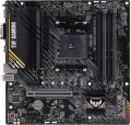
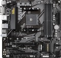
LED lighting
The presence of its own LED
backlight on the motherboard. This feature does not affect the functionality of the "motherboard", but gives it an unusual appearance. Therefore, it hardly makes sense for an ordinary user to specifically look for such a model (a
motherboard without backlighting is enough for him), but for modding lovers, backlighting can be very useful.
LED backlighting can take the form of individual lights or LED strips, come in different colours (sometimes with a choice of colours) and support additional effects — flashing, flickering, synchronization with other components (see "Lightning synchronization"), etc. Specific features depend on the motherboard model.
Lighting sync
Synchronization technology provided in the board with LED backlight (see above).
Synchronization itself allows you to "match" the backlight of the motherboard with the backlight of other system components — cases, video cards, keyboards, mice, etc. Thanks to this matching, all components can change colour synchronously, turn on / off at the same time, etc. Specific features the operation of such backlighting depends on the synchronization technology used, and, usually, each manufacturer has its own (Mystic Light Sync for MSI, RGB Fusion for Gigabyte, etc.). The compatibility of the components also depends on this: they must all support the same technology. So the easiest way to achieve backlight compatibility is to collect components from the same manufacturer.
Chipset
The chipset model installed in the motherboard. AMD's current chipset models are
B450,
A520,
B550,
X570,
A620,
B650,
B650E,
X670,
X670E,
B840,
B850,
X870,
X870E. For Intel, in turn, the list of chipsets looks like this:
X299,
H410,
B460,
H470,
Z490,
H510,
B560,
H570,
Z590,
H610,
B660,
H670,
Z690,
B760,
Z790,
H810,
B860,
Z890.
A chipset is a set of chips on the motherboard through which the individual components of the system inter
...act directly: the processor, RAM, drives, audio and video adapters, network controllers, etc. Technically, such a set consists of two parts — the north and south bridges. The key element is the northbridge, it connects the processor, memory, graphics card and the southbridge (together with the devices it controls). Therefore, it is often the name of the north bridge that is indicated as the chipset model, and the south bridge model is specified separately (see below); it is this scheme that is used in traditional layout motherboards, where bridges are made in the form of separate microcircuits. There are also solutions where both bridges are combined in one chip; for them, the name of the entire chipset can be indicated.
Anyway, knowing the chipset model, you can find various additional data on it — from general reviews to special instructions. An ordinary user, usually, does not need such information, but it can be useful for various professional tasks.Max. clock frequency
The maximum RAM clock speed supported by the motherboard. The actual clock frequency of the installed RAM modules should not exceed this indicator — otherwise, malfunctions are possible, and the capabilities of the “RAM” cannot be used to the fullest.
For modern PCs, a RAM frequency of
1500 – 2000 MHz or
less is considered very low,
2000 – 2500 MHz is modest,
2500 – 3000 MHz is average,
3000 – 3500 MHz is above average, and the most advanced boards can support frequencies of
3500 – 4000 MHz and even
more than 4000 MHz.
XMP
The ability of the motherboard to work with RAM modules that support
XMP (Extreme Memory Profiles) technology. This technology was developed by Intel; it is used in motherboards and RAM blocks and only works if both of these system components are XMP compliant. A similar technology from AMD is called AMP.
The main function of XMP is to facilitate system overclocking (“overclocking”): special overclocking profiles are “sewn” into the memory with this technology, and if desired, the user can only select one of these profiles without resorting to complex configuration procedures. This is not only easier, but also safer: every profile added to the bar is tested for stability.
M.2 connector
The number of M.2 connectors provided in the design of the motherboard. There are
motherboards for 1 M.2 connector,
for 2 connectors,
for 3 connectors or more.
The
M.2 connector is designed to connect advanced internal devices in a miniature form factor — in particular, high-speed SSD drives, as well as expansion cards like Wi-Fi and Bluetooth modules. However, connectors designed to connect only peripherals (Key E) are not included in this number. Nowadays, this is one of the most modern and advanced ways to connect components. But note that different interfaces can be implemented through this connector — SATA or PCI-E, and not necessarily both at once. See "M.2 interface" for details; here we note that SATA has a low speed and is used mainly for low-cost drives, while PCI-E is used for advanced solid-state modules and is also suitable for other types of internal peripherals.
Accordingly, the number of M.2 is the number of components of this format that can be simultaneously connected to the motherboard. At the same time, many modern boards, especially mid-range and top-end ones, are equipped with
two or more M.2 connectors, and moreover, with PCI-E support.
M.2
Electrical (logical) interfaces implemented through physical M.2 connectors on the motherboard.
See above for more details on such connectors. Here we note that they can work with two types of interfaces:
- SATA is a standard originally created for hard drives. M.2 usually supports the newest version, SATA 3; however, even it is noticeably inferior to PCI-E in terms of speed (600 MB / s) and functionality (only drives);
- PCI-E is the most common modern interface for connecting internal peripherals (otherwise NVMe). Suitable for both expansion cards (such as wireless adapters) and drives, while PCI-E speeds allow you to fully realize the potential of modern SSDs. The maximum communication speed depends on the version of this interface and on the number of lines. In modern M.2 connectors, you can find PCI-E versions 3.0 and 4.0, with speeds of about 1 GB / s and 2 GB / s per lane, respectively; and the number of lanes can be 1, 2 or 4 (PCI-E 1x, 2x and 4x respectively)
Specifically, the M.2 interface in the characteristics of motherboards is indicated by the number of connectors themselves and by the type of interfaces provided for in each of them. For example, the entry "3xSATA / PCI-E 4x" means three connectors that can work both in SATA format and in PCI-E 4x format; and the designation "1xSATA / PCI-E 4x, 1xPCI-E 2x" means two connectors, one of which works as SATA or PCI-E 4x, and the second — only as PCI-E 2x.
M.2 version
The version of the M.2 interface determines both the maximum data transfer rate and the supported devices that can be connected via physical M.2 connectors (see the corresponding paragraph).
The version of the M.2 interface in the specifications of motherboards is usually indicated by the number of connectors themselves and by the PCI-E revision provided for in each of them. For example, the entry “3x4.0” means three connectors capable of supporting PCI-E 4.0; and the designation “2x5.0, 1x4.0” means a trio of connectors, two of which support PCI-E 4.0, and another one supports PCI-E 5.0.
1x PCI-E slots
Number of PCI-E (PCI-Express) 1x slots installed on the motherboard. There are
motherboards for 1 PCI-E 1x slot,
2 PCI-E 1x slots,
3 PCI-E 1x ports and even more.
The PCI Express bus is used to connect various expansion cards — network and sound cards, video adapters, TV tuners and even SSD drives. The number in the name indicates the number of PCI-E lines (data transfer channels) supported by this slot; the more lines, the higher the throughput. Accordingly, PCI-E 1x is the basic, slowest version of this interface. The data transfer rate for such slots depends on the PCI-E version (see "PCI Express Support"): in particular, it is slightly less than 1 GB / s for version 3.0 and slightly less than 2 GB / s for 4.0.
Separately, we note that the general rule for PCI-E is as follows: the board must be connected to a slot with the same or more lines. Thus, only single-lane boards will be guaranteed to be compatible with PCI-E 1x.

