Motherboards Gigabyte
All Motherboards Advanced filters → |
Popular modelsCompare using chart →
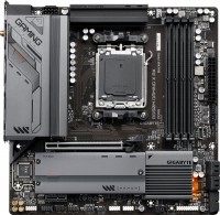
micro-ATX, socket AMD AM5, chipset AMD B650, 4 x DDR5, DIMM, 6400 MHz, USB C, HDMI, DisplayPort, M.2, LAN 2.5 Gbps, Wi-Fi, M.2 cooling, no backlight
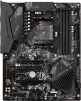
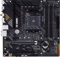
ATX, socket AMD AM4, chipset AMD B550, 4 x DDR4, DIMM, 4733 MHz, USB C, HDMI, M.2, no backlight
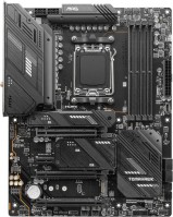
ATX, socket AMD AM5, chipset AMD X670E, 4 x DDR5, DIMM, 7800 MHz, USB C, HDMI, DisplayPort, M.2, LAN 2.5 Gbps, Wi-Fi, M.2 cooling, no backlight
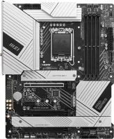
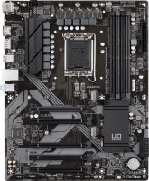
ATX, socket Intel LGA 1700, chipset Intel Z790, 4 x DDR5, DIMM, 7800 MHz, USB C, HDMI, DisplayPort, M.2, > 4 SATA3, LAN 2.5 Gbps, Wi-Fi, M.2 cooling, no backlight
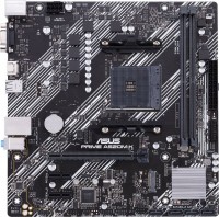
micro-ATX, socket AMD AM4, chipset AMD A520, 2 x DDR4, DIMM, 4600 MHz, USB C, HDMI, M.2, no backlight
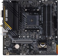
micro-ATX, socket AMD AM4, chipset AMD A520, 4 x DDR4, DIMM, 4866 MHz, USB C, HDMI, DisplayPort, M.2, Wi-Fi, M.2 cooling
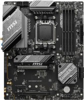
ATX, socket AMD AM5, chipset AMD B650, 4 x DDR5, DIMM, 7200 MHz, USB C, HDMI, DisplayPort, M.2, LAN 2.5 Gbps, CrossFire, Wi-Fi, M.2 cooling, no backlight
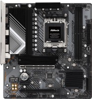
micro-ATX, socket AMD AM5, chipset AMD B650, 2 x DDR5, DIMM, 7200 MHz, USB C, HDMI, DisplayPort, M.2, LAN 2.5 Gbps, CrossFire, M.2 cooling, no backlight
micro-ATX, socket AMD AM5, chipset AMD B650, 4 x DDR5, DIMM, 7200 MHz, USB C, HDMI, DisplayPort, M.2, LAN 2.5 Gbps, CrossFire, Wi-Fi, M.2 cooling, no backlight
micro-ATX, socket AMD AM5, chipset AMD B650, 4 x DDR5, DIMM, 7200 MHz, USB C, HDMI, DisplayPort, M.2, LAN 2.5 Gbps, CrossFire, M.2 cooling, no backlight
ATX, socket AMD AM4, chipset AMD B550, 4 x DDR4, DIMM, 4733 MHz, USB C, HDMI, DisplayPort, M.2, LAN 2.5 Gbps, M.2 cooling
micro-ATX, socket AMD AM5, chipset AMD B650, 4 x DDR5, DIMM, 7600 MHz, USB C, HDMI, DisplayPort, M.2, LAN 2.5 Gbps, Wi-Fi, M.2 cooling, no backlight
micro-ATX, socket AMD AM4, chipset AMD B550, 4 x DDR4, DIMM, 4866 MHz, USB C, HDMI, DisplayPort, M.2, LAN 2.5 Gbps, Wi-Fi, M.2 cooling
ATX, socket Intel LGA 1700, chipset Intel B760, 4 x DDR4, DIMM, 5333 MHz, USB C, HDMI, DisplayPort, M.2, no backlight
You might be interested in
Articles, reviews, useful tips
All materials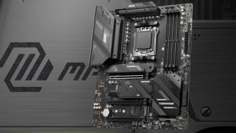
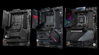
The best motherboards based on the AMD X670E chipset
Five high-end motherboards supporting Ryzen 7000 processors and DDR5 RAM

Building an affordable gaming PC for Company Of Heroes 3
Affordable gaming PC under $800 with Core i3-12100F, Radeon RX 6600 and 16GB RAM

Building an advanced gaming PC for Forspoken
Powerful PC with Ryzen 7 processor, GeForce RTX 4070 Ti graphics card and liquid cooling system
How to choose a motherboard?
Motherboard is the main part of any computer. Here's how to choose the right one for work, play and entertainment
How to properly build a PC yourself?
Quick course on building computers of varying levels of complexity for beginners and amateurs
Ryzen 7 7800X3D review: the new king of PC gaming
Let's see how AMD's new chip with "3D" cache breaks the competition in games
Motherboards: specifications, types
Show all
Features
The general specialization of the motherboard is the type of tasks for which it is optimized. It should be noted that the division according to this indicator is often rather conditional, models similar in characteristics may belong to different categories. However, the data on specialization greatly simplifies the choice.
In addition to the traditional "motherboards" for home and office, nowadays you can find solutions for high-end PCs (High-End Desktop) and for servers, as well as gaming boards and models for overclocking(the last two options are sometimes combined into one category , however, these are still different types of motherboards). There are also specialized models for cryptocurrency mining, but very few of them are produced — especially since many boards that originally had a different purpose are suitable for mining (see "Suitable for mining").
Here is a more detailed description of each variety:
— For home and office. Motherboards that do not belong to any of the more specific types. In general, this kind of "motherboards" is very diverse, it includes options from low-cost motherboards for modest office PCs to advanced models that come close to gaming and HEDT solutions. However, for the most part, solutions from this category...are designed for simple everyday tasks: working with documents, web surfing, 2D design and layout, games in low and medium quality, etc.
— Gamer's. Boards originally designed for use in advanced gaming PCs. In addition to high performance and compatibility with powerful components, primarily video cards (often several at once, in SLI and/or Crossfire format — see below), such models usually also have specific features of a gaming nature. The most noticeable of these features is the characteristic design, sometimes with backlighting and even backlight synchronization (see below), which allows you to organically fit the board into the original design of the gaming station. The functionality of gaming boards may include an advanced audio chip, a high-end network controller to reduce lags in online games, built-in software tools for tuning and optimizing performance, etc. Also, such models may provide advanced overclocking capabilities, sometimes not inferior to the capabilities of specialized boards for overclocking (see below). And sometimes the border between gaming and overclocking solutions is generally erased: for example, individual boards positioned by the manufacturer as gaming ones, in terms of functionality, can more likely be related to overclocking models.
— For overclocking. High-performance boards with an extended set of overclocking tools — improving system performance by fine-tuning individual components (mainly by increasing the clock frequencies used by these components). On most conventional motherboards, this setup involves considerable complexity and risk, it is usually an undocumented feature and is not covered by the warranty. However, in this case, the situation is the opposite: boards "for overclocking" are called so because the possibility of overclocking was originally incorporated in them by the manufacturer. One of the most noticeable features of such models is the presence in the firmware (BIOS) of special software tools for overclocking management, which makes overclocking as safe as possible and affordable even for inexperienced users. Another feature is improved compatibility with built-in overclocking tools provided in advanced processors, RAM modules, etc. Anyway, this particular type of board will be the best choice for those who want to build a fairly powerful PC with the ability to experiment in terms of performance.
— HEDT (High End Desktop). Motherboards designed for high-performance workstations and other PCs of a similar level. In many ways, they are similar to gaming ones and are sometimes even positioned as gaming ones, but they are designed more for general performance (including in professional tasks) than for confident work with games. One of the key features of such "motherboards" is the extensive functionality for working with RAM: they provide at least 4 slots for "RAM", and more often 6 or more, the maximum RAM frequency is at least 2500 MHz (and more often 4000 MHz and higher ), and the maximum volume is at least 128 GB. The rest of the characteristics are usually at a similar level. Also, the firmware may provide tools for overclocking, although in terms of this functionality, such boards are most often still inferior to overclockers. Note that such solutions can initially be positioned as gaming; the basis for categorization in the HEDT category in such cases is the fulfillment of the above criteria.
— For the server. Motherboards specially designed for servers. Such systems are noticeably different from conventional desktop PCs — in particular, they work with large volumes of drives and have increased requirements for the speed and reliability of data transfer; accordingly, to build servers, it is best to use specialized components, including motherboards. Among the main features of such motherboards are an abundance of slots for RAM (often more than 4), the ability to connect numerous drives (necessarily more than 4 SATA 3 slots, often 8 or more), as well as support for special technologies (like ECC — see below) . In addition, such boards can be made in specific form factors such as EEB or CEB (see "Form Factor"), although more traditional options are also found.
— Designed for mining. Motherboards specially designed for cryptocurrency mining (BitCoin, Ethereum, etc.). We emphasize that we are not just talking about the possibility of such an application (see “Suitable for mining”), but that the motherboard is initially positioned as a solution for creating a cryptocurrency “farm”. Recall that mining is the extraction of cryptocurrency by performing special calculations; such calculations are most conveniently carried out using several high-performance video cards at once. Accordingly, one of the distinguishing features of mining boards is the presence of several (usually at least 4) PCI-E 16x slots for connecting such video cards. However, this category of “motherboards” has not received much distribution: similar characteristics are also found among more general-purpose boards, it is quite possible to achieve performance sufficient for efficient mining on them.
Socket
The type of socket (socket for CPU) that the motherboard is equipped with. Different processor models correspond to different types of sockets, and before buying a motherboard, you should separately check whether the type of socket on it matches the type of socket for the desired processor.
Accordingly, motherboard manufacturers present platforms for current processors: Intel S1150, S1155, S1156, S1356, S1366, S2011, S2066, S1151, S1151 Coffee Lake, S3647, S1200, S1700.
And AMD: AM4, AM5, TR4 / TRX4.
Accordingly, motherboard manufacturers present platforms for current processors: Intel S1150, S1155, S1156, S1356, S1366, S2011, S2066, S1151, S1151 Coffee Lake, S3647, S1200, S1700.
And AMD: AM4, AM5, TR4 / TRX4.
Sockets
The number of sockets (sockets for CPUs) installed on the motherboard. Boards designed for use in conventional PCs usually have only one socket; boards designed for installation in workstations and servers and solving resource-intensive tasks can have up to 4 sockets and thus provide the installation of up to 4 processors in one system.
Form factor
The form factor of the motherboard determines, first of all, its physical dimensions, and, accordingly, a number of parameters directly related to them: type of computer case, installation method, type of power connector, number of slots for additional boards (expansion slots), etc. At the moment, there are such main form factors of motherboards:
— ATX. One of the most common form factors for PC motherboards. The standard size of such a board is 30.5x24.4 cm, it has up to 7 expansion slots and a 24-pin or (less often, in older models) 20-pin power connector.
— Micro-ATX. A slightly reduced version of the ATX form factor, with more compact dimensions (usually 24.4x24.4 cm) and, accordingly, fewer places for peripherals — there are usually only two slots for "RAM", expansion slots — from two to four. Nevertheless, despite the limited size, such boards can be intended for quite powerful systems.
— Mini-ITX. Motherboards of compact dimensions (17x17 cm). Designed for use primarily in small form factor computers (small form factor, SFF), in other words, compact PCs. According to the mounting specifications and the location of connectors and slots, they are compatible with ATX standard cases. They usually have one expansion slot.
— mini-STX. Another representative of compact form factors, assuming a boar...d size of 140x147 mm. Thus, the overall size is almost a third smaller than mini-ITX. At the same time, such motherboards often have seats for fairly powerful processors (for example, the LGA 1151 socket for Intel Core chips) and are made based on the corresponding TDP values. But expansion slots, usually, are absent.
— micro DTX. A relatively new compact form factor, which is not common, mainly among rather specific motherboards — in particular, models designed for cases in the PIO form factor. This form factor is characterized by a very small size and weight and allows you to mount the case directly behind the monitor, on a standard VESA mount. One of the features of "motherboards" for such systems is that the graphics card is installed along the board, and not perpendicularly — accordingly, the PCI-E 16x connector (see below) has a non-standard location. At the same time, micro-DTX boards are similar in terms of fasteners to microATX and can be used in cases of the corresponding form factor (except that additional equipment may be required for the correct installation of a graphics card). The standard size of such a board is 170 x 170 mm, similar to mini-ITX.
— mini DTX. An intermediate format between the microDTX described above and the original DTX; sometimes also described as an extended mini-ITX version. It has a standard size of 170 x 203 mm and can be equipped with two expansion slots (mini-ITX and mini-DTX have one such slot); it is completely similar in application — it is intended mainly for compact cases, in particular, HTPC computers.
— XL-ATX. Larger version of the ATX form factor. While not yet a common standard, size options include 32.5x24.4cm with 8 expansion slots and 34.3x26.2cm with up to 9 expansion slots.
— Thin mini-ITX. A “thin” version of the reduced mini-ITX form factor described above: according to the official specification, the total thickness of the thin mini-ITX board should not exceed 25 mm. Also designed for the most miniature computers — in particular, HTPC.
— E-ATX. The letter E in the name of this form factor stands for "Extended" — extended. True to its name, E-ATX is another enlarged version of ATX using 30.5x33cm boards.
— EEB. Full name SSI EEB. The form factor used in server systems (see “By direction”) provides a board size of 30.5x33 cm.
— CEB. The full name is SSI CEB. Another form factor of "server" motherboards. In fact, it is a narrower version of the EEB described above, with a width reduced to 25.9 cm (with the same height of 30.5 cm).
— flex-ATX. One of the compact variations of ATX, which provides board dimensions of less than 229x191 mm, as well as less than 3 expansion slots. At the same time, in terms of the location of the mounting holes, this standard is identical to microATX; in fact, it was developed as a potential replacement for the latter, but for a number of reasons it did not receive much distribution, although it continues to be produced.
— Non-standard (Custom). The name Proprietary is also used. Motherboards that do not conform to standard form factors and are designed for cases of special sizes (usually branded ones).
Power phases
The number of processor power phases provided on the motherboard.
Very simplistically, phases can be described as electronic blocks of a special design, through which power is supplied to the processor. The task of such blocks is to optimize this power, in particular, to minimize power surges when the load on the processor changes. In general, the more phases, the lower the load on each of them, the more stable the power supply and the more durable the electronics of the board. And the more powerful the CPU and the more cores it has, the more phases it needs; this number increases even more if the processor is planned to be overclocked. For example, for a conventional quad-core chip, only four phases are often enough, and for an overclocked one, at least eight may be needed. It is because of this that powerful processors can have problems when used on inexpensive low-phase motherboards.
Detailed recommendations on choosing the number of phases for specific CPU series and models can be found in special sources (including the documentation for CPU itself). Here we note that with numerous phases on the motherboard (more than 8), some of them can be virtual. To do this, real electronic blocks are supplemented with doublers or even triplers, which, formally, increases the number of phases: for example, 12 claimed phases can represent 6 physical blocks with doublers. However, virtual phases are much inferior to real ones in terms of capabilities — in fact, t...hey are just additions that slightly improve the characteristics of real phases. So, let's say, in our example, it is more correct to speak not about twelve, but only about six (though improved) phases. These nuances must be specified when choosing a motherboard.
VRM heatsink
The design of the motherboard has a separate heatsink for VRM.
VRM is a voltage regulation module through which power from a computer power supply is supplied to the processor. This module steps down the standard power supply voltage (+5V or +12V) to a lower value required by the processor (usually just over 1V). At high loads, the voltage regulator can get very hot, and without a specialized cooling system, the matter can end with overheating and even burnout of parts. The VRM heatsink reduces the likelihood of such situations; it can be useful for any CPU, and highly desirable if the board is planned to be used with a powerful high-end processor (especially overclocked).
VRM is a voltage regulation module through which power from a computer power supply is supplied to the processor. This module steps down the standard power supply voltage (+5V or +12V) to a lower value required by the processor (usually just over 1V). At high loads, the voltage regulator can get very hot, and without a specialized cooling system, the matter can end with overheating and even burnout of parts. The VRM heatsink reduces the likelihood of such situations; it can be useful for any CPU, and highly desirable if the board is planned to be used with a powerful high-end processor (especially overclocked).
Heat pipes
The heat pipe is a hermetically sealed structure containing a low-boiling liquid. When one end of the tube is heated, this liquid evaporates and condenses at the other end, thus removing heat from the heating source and transferring it to the radiator. Such devices are simple and at the same time effective, so they can be easily used as an addition to radiators.
Liquid cooling
The presence of a water cooling system indicates the "hot" purpose of the motherboard. This option makes sense only in the most powerful gaming builds, as well as systems with the potential for further "overclocking" — that is, in configurations for which traditional air cooling with coolers is not enough.
Integrated CPU
The motherboard has its own processor. On the one hand, this saves the user from having to purchase a processor separately and from problems with processor and motherboard compatibility. On the other hand, embedded processors are most often found on compact mini-ITX motherboards (see Form Factor), and the processors themselves are usually energy-efficient models with rather poor performance characteristics.
Integrated CPU model
The name of the integrated processor installed in the motherboard with the corresponding function. Knowing the exact name of the model, you can find its detailed characteristics, reviews, test results and other information, and thus evaluate how this processor corresponds to the desired system performance. This feature is especially useful if the computer for which the motherboard is purchased is planned to be used to solve specific problems.
Metal backplate
The presence of a metal backplate in the design of the motherboard.
The backplate is a special plate located on the back side of the board (that is, on the opposite side from the connection slots). This feature is typical mainly for advanced "motherboards" designed for powerful systems: individual components of such systems (especially cooling) can be very heavy, and installing them directly on the board would be fraught with damage to it. And the metal backplate avoids this: it plays the role of an additional support that removes the main load from the motherboard. At the same time, such a plate is usually made thick and elastic enough to transfer even a very significant weight of components without consequences.
The backplate is a special plate located on the back side of the board (that is, on the opposite side from the connection slots). This feature is typical mainly for advanced "motherboards" designed for powerful systems: individual components of such systems (especially cooling) can be very heavy, and installing them directly on the board would be fraught with damage to it. And the metal backplate avoids this: it plays the role of an additional support that removes the main load from the motherboard. At the same time, such a plate is usually made thick and elastic enough to transfer even a very significant weight of components without consequences.
POST encoder
Standard digital indication system for displaying POST codes for motherboard initialization. Thanks to the POST encoder, you can easily determine which component has a problem.
LED lighting
The presence of its own LED backlight on the motherboard. This feature does not affect the functionality of the "motherboard", but gives it an unusual appearance. Therefore, it hardly makes sense for an ordinary user to specifically look for such a model (a motherboard without backlighting is enough for him), but for modding lovers, backlighting can be very useful.
LED backlighting can take the form of individual lights or LED strips, come in different colours (sometimes with a choice of colours) and support additional effects — flashing, flickering, synchronization with other components (see "Lightning synchronization"), etc. Specific features depend on the motherboard model.
LED backlighting can take the form of individual lights or LED strips, come in different colours (sometimes with a choice of colours) and support additional effects — flashing, flickering, synchronization with other components (see "Lightning synchronization"), etc. Specific features depend on the motherboard model.
Lighting sync
Synchronization technology provided in the board with LED backlight (see above).
Synchronization itself allows you to "match" the backlight of the motherboard with the backlight of other system components — cases, video cards, keyboards, mice, etc. Thanks to this matching, all components can change colour synchronously, turn on / off at the same time, etc. Specific features the operation of such backlighting depends on the synchronization technology used, and, usually, each manufacturer has its own (Mystic Light Sync for MSI, RGB Fusion for Gigabyte, etc.). The compatibility of the components also depends on this: they must all support the same technology. So the easiest way to achieve backlight compatibility is to collect components from the same manufacturer.
Synchronization itself allows you to "match" the backlight of the motherboard with the backlight of other system components — cases, video cards, keyboards, mice, etc. Thanks to this matching, all components can change colour synchronously, turn on / off at the same time, etc. Specific features the operation of such backlighting depends on the synchronization technology used, and, usually, each manufacturer has its own (Mystic Light Sync for MSI, RGB Fusion for Gigabyte, etc.). The compatibility of the components also depends on this: they must all support the same technology. So the easiest way to achieve backlight compatibility is to collect components from the same manufacturer.
Size (HxW)
Motherboard dimensions in height and width. It is assumed that the traditional placement of motherboards is vertical, so in this case one of the dimensions is called not the length, but the height.
Motherboard sizes are largely determined by their form factors (see above), however, the size of a particular motherboard may differ slightly from the standard adopted for this form factor. In addition, it is usually easier to clarify the dimensions according to the characteristics of a particular motherboard than to look for or remember general information on the form factor. Therefore, size data can be given even for models that fully comply with the standard.
The third dimension — thickness — is considered less important for a number of reasons, so it is often omitted.
Chipset
The chipset model installed in the motherboard. AMD's current chipset models are B450, A520, B550, X570, X570S, A620, B650, B650E, X670 and X670E. For Intel, in turn, the list of chipsets looks like this: X299, H410, B460, H470, Z490, H510, B560, H570, Z590, H610, B660, H670, Z690, B760, Z790.
A chipset is a set of chips on the motherboard through which the individual components of the system interact directly: the processor, RAM, drives, audio and video adapters, network controllers, etc. Technically, such a set consists of two parts — the north and south bridges. The key element is the northbridge, it connects the processor, mem...ory, graphics card and the southbridge (together with the devices it controls). Therefore, it is often the name of the north bridge that is indicated as the chipset model, and the south bridge model is specified separately (see below); it is this scheme that is used in traditional layout motherboards, where bridges are made in the form of separate microcircuits. There are also solutions where both bridges are combined in one chip; for them, the name of the entire chipset can be indicated.
Anyway, knowing the chipset model, you can find various additional data on it — from general reviews to special instructions. An ordinary user, usually, does not need such information, but it can be useful for various professional tasks.
Southbridge
Model of the south bridge installed in the motherboard.
This component of the "motherboard" is one of the constituent parts of the chipset. See above for details on the chipset; here we note that the south bridge is responsible for the interaction of the motherboard with peripheral devices: expansion cards (sound, network), drives, external USB peripherals, etc. Knowing the name of this module, if necessary, you can easily find detailed information about its characteristics and capabilities. An ordinary user, usually, does not need such information, but it can be useful for various professional tasks.
This component of the "motherboard" is one of the constituent parts of the chipset. See above for details on the chipset; here we note that the south bridge is responsible for the interaction of the motherboard with peripheral devices: expansion cards (sound, network), drives, external USB peripherals, etc. Knowing the name of this module, if necessary, you can easily find detailed information about its characteristics and capabilities. An ordinary user, usually, does not need such information, but it can be useful for various professional tasks.
BIOS
The type of BIOS installed on the motherboard. Note that only “classic” BIOSes are taken into account here — from Ami, from Award and from Intel; a more advanced UEFI BIOS has been moved to a separate item (see below).
The BIOS is the basic input/output system, the motherboard's own software firmware stored in its permanent memory; it allows all the hardware components of the system to interact with each other, even if the computer does not have an OS installed. In other words, it is the “bios” that controls the computer from the moment it is turned on until the operating system boots. This firmware also includes a set of tools for changing the basic settings.
Speaking about specific varieties, it is worth saying that the mentioned "classic" firmware do not have fundamental differences between themselves; in addition, the set of features is largely determined not by the type of BIOS, but by the model of the motherboard. Therefore, the type of BIOS is not a key choice; even for professionals and enthusiasts, it rarely turns out to be fundamental.
DualBIOS
Motherboard support for DualBIOS technology.
Crashes and errors in the BIOS (see BIOS) are one of the most serious problems that can occur with a modern PC — they not only make the computer unusable, but also very difficult to fix. DualBIOS technology is designed to make it easier to deal with such problems. Motherboards made using this technology have two chips for writing the BIOS: the first chip contains the main BIOS version, which is used to boot the system in normal mode, the second one contains a backup copy of the BIOS in the original (factory) configuration. The backup chip comes into operation if an error is detected in the main BIOS: if an error is detected in the programme code, it is restored to the original factory version, but if there was a hardware failure, the backup chip takes control of the system, replacing the main one. This allows you to keep your system up and running even in the event of serious BIOS problems without resorting to complex recovery procedures.
Crashes and errors in the BIOS (see BIOS) are one of the most serious problems that can occur with a modern PC — they not only make the computer unusable, but also very difficult to fix. DualBIOS technology is designed to make it easier to deal with such problems. Motherboards made using this technology have two chips for writing the BIOS: the first chip contains the main BIOS version, which is used to boot the system in normal mode, the second one contains a backup copy of the BIOS in the original (factory) configuration. The backup chip comes into operation if an error is detected in the main BIOS: if an error is detected in the programme code, it is restored to the original factory version, but if there was a hardware failure, the backup chip takes control of the system, replacing the main one. This allows you to keep your system up and running even in the event of serious BIOS problems without resorting to complex recovery procedures.
UEFI BIOS
The presence of UEFI BIOS firmware on the motherboard.
Such firmware is usually combined with one of the classic "bios" (see BIOS). In fact, it is an additional add-on that expands the BIOS and makes it more convenient to manage. In some ways, UEFI approaches a full-fledged operating system: it has a convenient and understandable graphical interface even for a non-specialist, supports mouse control, is equipped with an extensive set of tools, and in some versions there is even the ability to access the Internet. In addition, this firmware takes into account all the features of modern computer hardware — including those that have appeared recently and are not covered in earlier, traditional BIOSes.
Such firmware is usually combined with one of the classic "bios" (see BIOS). In fact, it is an additional add-on that expands the BIOS and makes it more convenient to manage. In some ways, UEFI approaches a full-fledged operating system: it has a convenient and understandable graphical interface even for a non-specialist, supports mouse control, is equipped with an extensive set of tools, and in some versions there is even the ability to access the Internet. In addition, this firmware takes into account all the features of modern computer hardware — including those that have appeared recently and are not covered in earlier, traditional BIOSes.
Active cooling
The presence of its own built-in active cooling system.
Active cooling is called, in which heat is forcibly removed from a heated object and this function is usually provided with the help of fans. This solution is designed to reduce the thermal load on motherboards without external coolers, which anyway will be additionally installed.
Active cooling is called, in which heat is forcibly removed from a heated object and this function is usually provided with the help of fans. This solution is designed to reduce the thermal load on motherboards without external coolers, which anyway will be additionally installed.
DDR3
The number of slots for DDR3 memory sticks provided in the motherboard.
DDR3 is the third generation of RAM with the so-called double data transfer. Some time ago, this standard was the most popular in computer technology, but now it is increasingly losing ground to the newer and more advanced DDR4. However, DDR3 boards are still on the market; they can have 2, 4, or even 6 or more slots for such memory.
DDR3 is the third generation of RAM with the so-called double data transfer. Some time ago, this standard was the most popular in computer technology, but now it is increasingly losing ground to the newer and more advanced DDR4. However, DDR3 boards are still on the market; they can have 2, 4, or even 6 or more slots for such memory.
DDR4
The number of slots for DDR4 memory sticks provided in the motherboard.
DDR4 is a further (after the third version) development of the DDR standard, released in 2014. Improvements compared to DDR3 are traditional — an increase in operating speed and a decrease in power consumption; The volume of one module can be from 2 to 128 GB. It is this RAM standard that most modern motherboards are designed for; the number of slots for DDR4 is usually 2 or 4, less often — 6 or more.
DDR4 is a further (after the third version) development of the DDR standard, released in 2014. Improvements compared to DDR3 are traditional — an increase in operating speed and a decrease in power consumption; The volume of one module can be from 2 to 128 GB. It is this RAM standard that most modern motherboards are designed for; the number of slots for DDR4 is usually 2 or 4, less often — 6 or more.
DDR5
The number of slots for DDR5 RAM, provided in the motherboard.
DDR5 is being introduced to replace the fourth version of the DDR standard from the end of 2020. It provides for approximately a twofold increase in memory subsystem performance and increased bandwidth compared to DDR4. Instead of a single 64-bit data channel, DDR5 uses a pair of independent 32-bit channels that work with 16-byte packets and allow 64 bytes of information to be delivered per clock on each channel. New memory modules require a voltage of 1.1 V, and the maximum volume of one DDR5 bar can reach an impressive 128 GB.
DDR5 is being introduced to replace the fourth version of the DDR standard from the end of 2020. It provides for approximately a twofold increase in memory subsystem performance and increased bandwidth compared to DDR4. Instead of a single 64-bit data channel, DDR5 uses a pair of independent 32-bit channels that work with 16-byte packets and allow 64 bytes of information to be delivered per clock on each channel. New memory modules require a voltage of 1.1 V, and the maximum volume of one DDR5 bar can reach an impressive 128 GB.
Memory module
The form factor of the RAM sticks for which the corresponding slots on the motherboard are designed. Different form factors imply a difference not only in size, but also in the arrangement of contacts, which is why they are incompatible with each other; this must be taken into account when selecting components.
— DIMM. Abbreviation for Dual In-Line Memory Module. This form factor can be called "full-size", it is standard for desktops and is quite popular among motherboards of all sizes.
— SO-DIMM. Abbreviation for "Small Outline Dual In-Line Memory Module", which can be roughly translated as "a smaller version of DIMM"; accordingly, the main external differences between the brackets and the slots for them are the reduced size and number of contacts. This option is used in compact form factor motherboards, most often mini-ITX (see above).
Operation mode
The mode of operation of the motherboard with RAM installed on it. It may be as follows:
— Single channel. The simplest mode of operation: one controller works immediately with the entire amount of RAM. The main advantages of this mode are the simplicity and low cost of controllers. However, its performance is very low, so single-channel "motherboards" are extremely rare nowadays — mainly among inexpensive models for home / office.
— Dual channel. In this mode, two independent controllers work with RAM, the memory itself is divided into two blocks, and information is exchanged in two streams, which increases the speed of operation. Performance gains can range from 5-10% to 100%, depending on the specific application and system features. Note that two RAM sticks with identical characteristics are highly desirable for dual-channel operation — this allows you to achieve optimal performance, in addition, not all "motherboards" are able to work with pairs of unequal memory modules.
— Two / three-channel. Motherboards that support three-channel RAM. This mode is similar to dual-channel and fundamentally differs only in the number of threads and memory bars — there must be 3 of them (or a number that is a multiple of 3). At the same time, again, ideally, such strips should be the same; the possibility of using different brackets is not guaranteed in all motherboards, and if the frequency does not match, the channel speed will be limited by the spe...ed of the slowest RAM module. If only two compatible brackets are installed, the system will operate in dual-channel mode.
— Two / four-channel. Motherboards that support quad-channel RAM. This mode is completely similar to the two/three-channel mode described above and differs only in the number of RAM modules — they need 4 (or a multiple of four). At the same time, again, when installing a smaller number of slats, such a motherboard can operate in the appropriate mode — two or three-channel (the main thing is that the slats meet the requirements for this mode).
— Six-channel. An operating mode that assumes the presence of 6 separate memory controllers and a multiple number of slots for individual modules (12 in some boards, more theoretically possible). It is found exclusively in top-end solutions, usually of the HEDT class (see "By Direction"), designed for uncompromising performance.
Max. clock frequency
The maximum RAM clock speed supported by the motherboard. The actual clock frequency of the installed RAM modules should not exceed this indicator — otherwise, malfunctions are possible, and the capabilities of the “RAM” cannot be used to the fullest.
For modern PCs, a RAM frequency of 1500 – 2000 MHz or less is considered very low, 2000 – 2500 MHz is modest, 2500 – 3000 MHz is average, 3000 – 3500 MHz is above average, and the most advanced boards can support frequencies of 3500 – 4000 MHz and even more than 4000 MHz.
For modern PCs, a RAM frequency of 1500 – 2000 MHz or less is considered very low, 2000 – 2500 MHz is modest, 2500 – 3000 MHz is average, 3000 – 3500 MHz is above average, and the most advanced boards can support frequencies of 3500 – 4000 MHz and even more than 4000 MHz.
Max. memory
The maximum amount of RAM that can be installed on the motherboard.
When choosing according to this parameter, it is important to take into account the planned use of the PC and the real needs of the user. So, volumes up to 32 GB inclusive are quite enough to solve any basic problems and run games comfortably, but without a significant reserve for an upgrade. 64 GB is the optimal option for many professional use cases, and for the most resource-intensive tasks like 3D rendering, 96 GB or even 128 GB of memory will not be a limit. The most “capacious” motherboards are compatible with volumes of 192 GB or more - they are mainly top-end solutions for servers and HEDT (see “In the direction”).
You can choose this parameter with a reserve – taking into account a potential RAM upgrade, because installing additional RAM sticks is the simplest way to increase system performance. Taking this factor into account, many relatively simple motherboards support very significant amounts of RAM.
AMP
The ability of the motherboard to work with RAM modules that support AMP technology (AMD Memory Profiles). This technology was developed by AMD; it is used in motherboards and RAM blocks and only works if both of these system components are AMP compatible. A similar technology from Intel is called XMP.
The main function of AMP is to facilitate system overclocking (“overclocking”): special overclocking profiles are “sewn” into memory with this technology, and if desired, the user can only select one of these profiles without resorting to complex configuration procedures. This is not only easier, but also safer: every profile added to the bar is tested for stability.
The main function of AMP is to facilitate system overclocking (“overclocking”): special overclocking profiles are “sewn” into memory with this technology, and if desired, the user can only select one of these profiles without resorting to complex configuration procedures. This is not only easier, but also safer: every profile added to the bar is tested for stability.
XMP
The ability of the motherboard to work with RAM modules that support XMP (Extreme Memory Profiles) technology. This technology was developed by Intel; it is used in motherboards and RAM blocks and only works if both of these system components are XMP compliant. A similar technology from AMD is called AMP.
The main function of XMP is to facilitate system overclocking (“overclocking”): special overclocking profiles are “sewn” into the memory with this technology, and if desired, the user can only select one of these profiles without resorting to complex configuration procedures. This is not only easier, but also safer: every profile added to the bar is tested for stability.
The main function of XMP is to facilitate system overclocking (“overclocking”): special overclocking profiles are “sewn” into the memory with this technology, and if desired, the user can only select one of these profiles without resorting to complex configuration procedures. This is not only easier, but also safer: every profile added to the bar is tested for stability.
EXPO support
Memory module compatibility with EXPO technology (Extended Profiles for Overclocking). It was created at AMD by a specialist for overclocking DDR5 strips as part of Ryzen 7000 systems. At its core, this is a factory set of RAM profiles that simplifies overclocking the “RAM”. EXPO support improves gaming flow Rate by approximately 11% at Full HD broadcast resolution.
ECC
The ability of the motherboard to work with memory modules that support ECC (Error Checking and Correction) technology. This technology allows you to correct minor errors that occur in the process of working with data, and increases the overall reliability of the system; mainly used in servers.
SATA 3 (6Gbps)
Number of SATA 3 ports on the motherboard.
SATA is now the standard interface for connecting internal drives (mainly HDDs) and optical drives. One device is connected to one such connector, so the number of SATA ports corresponds to the number of internal drives / drives that can be connected to the motherboard through such an interface. A large number ( 6 SATA ports and more) is necessary in case of active use of several hard drives and other peripherals. For domestic use, 4 is enough. SATA 3, as the name suggests, is the third version of this interface, operating at a total speed of about 6 Gbps; the useful speed, taking into account the redundancy of the transmitted data, is about 4.8 Mbps (600 MB / s) — that is, twice as much as in SATA 2.
Note that different SATA standards are quite compatible with each other in both directions: older drives can be connected to newer ports, and vice versa. The only thing is that the data transfer rate will be limited by the capabilities of the slower version, and in some cases it may be necessary to reconfigure the drives with hardware (switches, jumpers) or software. It is also worth saying that SATA 3 is the newest and most advanced variation of SATA today, but the capabilities of this standard are not enough to unlock the full potential of high-speed SSDs. Therefore, SATA 3 is mainly used for hard drives and low-cost SSDs, faster drives are conn...ected to specially designed connectors like M.2 or U.2 (see below).
mSATA
The number of mSATA connectors provided in the design of the motherboard.
The mSATA(mini-SATA) interface is mainly used to connect solid state drives (SSD) in the form factor of the same name. Such drives have a very miniature size — 50.95 x 30 x 3 mm. However, the capabilities of the interface itself are limited by the capabilities of SATA, so nowadays it is gradually being replaced by more advanced standards — primarily M.2 (see below).
Note also that mSATA is physically identical to the mini PCI-E interface, however these standards are not electrically compatible.
M.2 connector
The number of M.2 connectors provided in the design of the motherboard. There are motherboards for 1 M.2 connector, for 2 connectors, for 3 connectors or more.
The M.2 connector is designed to connect advanced internal devices in a miniature form factor — in particular, high-speed SSD drives, as well as expansion cards like Wi-Fi and Bluetooth modules. However, connectors designed to connect only peripherals (Key E) are not included in this number. Nowadays, this is one of the most modern and advanced ways to connect components. But note that different interfaces can be implemented through this connector — SATA or PCI-E, and not necessarily both at once. See "M.2 interface" for details; here we note that SATA has a low speed and is used mainly for low-cost drives, while PCI-E is used for advanced solid-state modules and is also suitable for other types of internal peripherals.
Accordingly, the number of M.2 is the number of components of this format that can be simultaneously connected to the motherboard. At the same time, many modern boards, especially mid-range and top-end ones, are equipped with two or more M.2 connectors, and moreover, with PCI-E support.
M.2
Electrical (logical) interfaces implemented through physical M.2 connectors on the motherboard.
See above for more details on such connectors. Here we note that they can work with two types of interfaces:
See above for more details on such connectors. Here we note that they can work with two types of interfaces:
- SATA is a standard originally created for hard drives. M.2 usually supports the newest version, SATA 3; however, even it is noticeably inferior to PCI-E in terms of speed (600 MB / s) and functionality (only drives);
- PCI-E is the most common modern interface for connecting internal peripherals (otherwise NVMe). Suitable for both expansion cards (such as wireless adapters) and drives, while PCI-E speeds allow you to fully realize the potential of modern SSDs. The maximum communication speed depends on the version of this interface and on the number of lines. In modern M.2 connectors, you can find PCI-E versions 3.0 and 4.0, with speeds of about 1 GB / s and 2 GB / s per lane, respectively; and the number of lanes can be 1, 2 or 4 (PCI-E 1x, 2x and 4x respectively)
Interface version M.2
The version of the M.2 interface determines both the maximum data transfer rate and the supported devices that can be connected via physical M.2 connectors (see the corresponding paragraph).
The version of the M.2 interface in the specifications of motherboards is usually indicated by the number of connectors themselves and by the PCI-E revision provided for in each of them. For example, the entry “3x4.0” means three connectors capable of supporting PCI-E 4.0; and the designation “2x5.0, 1x4.0” means a trio of connectors, two of which support PCI-E 4.0, and another one supports PCI-E 5.0.
The version of the M.2 interface in the specifications of motherboards is usually indicated by the number of connectors themselves and by the PCI-E revision provided for in each of them. For example, the entry “3x4.0” means three connectors capable of supporting PCI-E 4.0; and the designation “2x5.0, 1x4.0” means a trio of connectors, two of which support PCI-E 4.0, and another one supports PCI-E 5.0.
M.2 SSD cooling
Motherboard-integrated cooling for M.2 SSD drives.
This connector allows you to achieve high speed, however, for the same reason, many M.2 SSDs have high heat dissipation, and additional cooling may be required to avoid overheating. Most often, the simplest radiator in the form of a metal plate is responsible for such cooling — in the case of an SSD, this is quite enough.
This connector allows you to achieve high speed, however, for the same reason, many M.2 SSDs have high heat dissipation, and additional cooling may be required to avoid overheating. Most often, the simplest radiator in the form of a metal plate is responsible for such cooling — in the case of an SSD, this is quite enough.
U.2 connector
The number of U.2 connectors provided in the design of the motherboard.
U.2 is a specialized connector for connecting internal drives — primarily modern SSD modules that support high-speed NVMe data transfer technology. Such an interface can support up to 4 PCI-E lanes (see PCI-E 4x slots) and up to 2 SATA 3 lanes (see above). Note that in fact, U.2 is mainly used in 2.5" form factor drives installed in case slots and connected to the board with a cable. Due to their large size, such drives generally become more capacious than M.2 modules. (see above).
U.2 is a specialized connector for connecting internal drives — primarily modern SSD modules that support high-speed NVMe data transfer technology. Such an interface can support up to 4 PCI-E lanes (see PCI-E 4x slots) and up to 2 SATA 3 lanes (see above). Note that in fact, U.2 is mainly used in 2.5" form factor drives installed in case slots and connected to the board with a cable. Due to their large size, such drives generally become more capacious than M.2 modules. (see above).
eSATA connector
The number of eSATA ports on the motherboard.
eSATA is a type of SATA interface designed to connect external drives. Accordingly, connectors of this type are usually located on the rear panel of the motherboard, freely accessible from the outside. However, nowadays, this interface is considered obsolete and is gradually falling into disuse, being replaced by faster and more advanced standards — primarily USB 3.2 of different generations (see below).
eSATA is a type of SATA interface designed to connect external drives. Accordingly, connectors of this type are usually located on the rear panel of the motherboard, freely accessible from the outside. However, nowadays, this interface is considered obsolete and is gradually falling into disuse, being replaced by faster and more advanced standards — primarily USB 3.2 of different generations (see below).
SAS connector
The number of SAS ports on the motherboard.
SAS is a modification of the SCSI interface and is usually used to connect drives. Devices with this interface are mainly used in server systems and are practically not found in ordinary desktop PCs. The data transfer rate reaches 6 Gbps (750 Mb/s). It is worth noting that SATA2 and SATA3 drives (see the relevant glossary entries) can be connected to the SAS interface; at the same time, a SAS device cannot be connected to the SATA interface.
SAS is a modification of the SCSI interface and is usually used to connect drives. Devices with this interface are mainly used in server systems and are practically not found in ordinary desktop PCs. The data transfer rate reaches 6 Gbps (750 Mb/s). It is worth noting that SATA2 and SATA3 drives (see the relevant glossary entries) can be connected to the SAS interface; at the same time, a SAS device cannot be connected to the SATA interface.
Included drive size
The amount of storage that comes with the motherboard.
Such equipment is found mainly in high-end gaming boards (see "Intended use"). As complete drives, SSD modules are usually used; they are not intended for large volumes of information, their main task is to store the most critical data to speed up access to them. Therefore, the volumes of such media are usually small — most often 16 or 32 GB: this is quite enough for the purposes mentioned.
Such equipment is found mainly in high-end gaming boards (see "Intended use"). As complete drives, SSD modules are usually used; they are not intended for large volumes of information, their main task is to store the most critical data to speed up access to them. Therefore, the volumes of such media are usually small — most often 16 or 32 GB: this is quite enough for the purposes mentioned.
Integrated RAID controller
The presence of a built-in RAID controller on the motherboard. This function allows you to create RAID arrays from drives connected to the system using only the tools of the motherboard itself, in other words, through the standard BIOS or UEFI (see above), without using additional hardware or software.
RAID is a set (array) of several interconnected drives, perceived by the system as a whole. Depending on the type of RAID, it can provide an increase in read speed or increased reliability of information storage. Here are some of the more popular types:
— RAID 0 — data is written one by one to each of the connected disks (one file may be written to different disks). Provides performance improvements, but not fault tolerance.
— RAID 1 — information written to one of the disks is "mirrored" on all the others. Provides increased reliability by reducing system effective capacity.
— RAID 5 — information is written one by one, as in RAID 0, however, in addition to the main data, the so-called disks are also written to disks. checksums that allow you to restore information in the event of a complete failure of one of the disks. It has good fault tolerance and does not reduce the useful volume of disks as much as RAID 1, however, it is relatively slow and requires a minimum of 3 disks (two are enough for the previous types).
There are other varieties, they are used less often. Different motherb...oards may support different types of RAID, so before buying a model with this feature, it's ok to check the details separately.
1x PCI-E slots
Number of PCI-E (PCI-Express) 1x slots installed on the motherboard. There are motherboards for 1 PCI-E 1x slot, 2 PCI-E 1x slots, 3 PCI-E 1x ports and even more.
The PCI Express bus is used to connect various expansion cards — network and sound cards, video adapters, TV tuners and even SSD drives. The number in the name indicates the number of PCI-E lines (data transfer channels) supported by this slot; the more lines, the higher the throughput. Accordingly, PCI-E 1x is the basic, slowest version of this interface. The data transfer rate for such slots depends on the PCI-E version (see "PCI Express Support"): in particular, it is slightly less than 1 GB / s for version 3.0 and slightly less than 2 GB / s for 4.0.
Separately, we note that the general rule for PCI-E is as follows: the board must be connected to a slot with the same or more lines. Thus, only single-lane boards will be guaranteed to be compatible with PCI-E 1x.
PCI-E 4x slots
Number of PCI-E (PCI-Express) 4x slots installed on the motherboard.
The PCI Express bus is used to connect various expansion cards — network and sound cards, video adapters, TV tuners and even SSD drives. The number in the name indicates the number of PCI-E lines (data transfer channels) supported by this slot; the more lines, the higher the throughput. 4 PCI-E lanes provide data transfer speeds of about 4 GB/s for PCI-E version 3.0 and 8 GB/s for version 4.0 (for more information about the versions, see "PCI Express Support").
The general rule for PCI-E is this: the card must be connected to a slot with the same or more lanes. Thus, boards for 1 or 4 PCI Express lanes can be installed in a standard PCI-E 4x slot. However, it is worth noting that in the design of modern "motherboards" there are slots of increased sizes — in particular, PCI-E 4x, corresponding in size to PCI-E 16x. The type of such slots in our catalog is indicated by the actual throughput, that is, the mentioned example will also be counted as PCI-E 4x. At the same time, peripherals with 16 PCI-E channels can also be physically connected to this connector — however, you should make sure that the throughput will be sufficient for the normal operation of such peripherals.
PCI-E 8x slots
The number of PCI-E 8x slots installed on the motherboard. This is an eight-lane version of the PCI-Express connection bus, with a minimum throughput of 16 Gbps one way (32 Gbps both). For more information about the PCI-Express standard, see "PCI-E 1x Slots".
PCI-E 16x slots
Number of PCI-E (PCI-Express) 16x slots installed on the motherboard.
The PCI Express bus is used to connect various expansion cards — network and sound cards, video adapters, TV tuners and even SSD drives. The number in the name indicates the number of PCI-E lines (data transfer channels) supported by this slot; the more lines, the higher the throughput. 16 lanes is the largest number found in modern PCI Express slots and cards (more is technically possible, but the connectors would be too bulky). Accordingly, these slots are the fastest: they have a data transfer rate of 16 GB / s for PCI-E 3.0 and 32 GB / s for version 4.0 (for more information about the versions, see "PCI Express Support").
Separately, we note that it is PCI-E 16x that is considered the optimal connector for connecting video cards. However, when choosing a motherboard with several such slots, it is worth considering the PCI-E modes supported by it (see below). In addition, we recall that the PCI Express interface allows you to connect boards with a smaller number of lines to connectors with numerous lines. Thus, PCI-E 16x will fit any PCI Express card.
It is also worth mentioning that in the design of modern "motherboards" there are slots of increased sizes — in particular, PCI-E 4x, corresponding in size to PCI-E 16x. However, the type of PCI-E slots in our catalog is indicated by the actual throughput; so only connectors that support 16x speed are considered as PCI-E 16x.
PCI Modes
Operating modes of PCI-E 16x slots supported by the motherboard.
For more information about this interface, see above, and information about the modes is indicated if there are several PCI-E 16x slots on the board. This data specifies at what speed these slots can operate when expansion cards are connected to them at the same time, how many lines each of them can use. The fact is that the total number of PCI-Express lanes on any motherboard is limited, and they are usually not enough for the simultaneous operation of all 16-channel slots at full capacity. Accordingly, when working simultaneously, the speed inevitably has to be limited: for example, recording 16x / 4x / 4x means that the motherboard has three 16-channel slots, but if three video cards are connected to them at once, then the second and third slots will be able to give speed only to PCI-E 4x level. Accordingly, for a different number of slots and the number of digits will be appropriate. There are also boards with several modes — for example, 16x/0x/4 and 8x/8x/4x (0x means that the slot becomes inoperable altogether).
You have to pay attention to this parameter mainly when installing several video cards at the same time: in some cases (for example, when using SLI technology), for correct operation of video adapters, they must be connected to slots at the same speed.
PCI Express
The version of the PCI Express interface supported by the motherboard. Recall that nowadays this interface is actually the standard for connecting video cards and other expansion cards. It can have a different number of lines — usually 1x, 4x and/or 16x; see the relevant paragraphs above for more details. Here we note that the version depends primarily on the data transfer rate per line. The most relevant options are:
— PCI Express 3.0. A version released back in 2010 and implemented in hardware two years later. One of the key differences from the previous PCI E 2.0 was the use of 128b / 130b encoding, that is, in every 130 bits — 128 main and two service bits (instead of 8b / 10b, which was used earlier and gave very high redundancy). This made it possible to almost double the data transfer rate (up to 984 Mbps versus 500 Mbps per 1 PCI-E lane) with a relatively small increase in the number of transactions per second (up to 8 GT/s versus 5 GT/s). Despite the introduction of the newer version 4.0, the PCI-E 3.0 standard is still quite popular in modern motherboards.
— PCI Express 4.0. Another PCI-E update introduced in 2017; the first "motherboards" with support for this version appeared in late spring 2019. Compared to PCI-E 3.0, the data transfer rate in PCI-E 4.0 has been doubled to 1969 Mbps per PCI-E lane.
— PCI Express 5.0. The evoluti...onary development of the PCI Express 5.0 standard, the final specification of which was approved in 2019, and its implementation in hardware began to be implemented in 2021. If we draw parallels with PCI E 4.0, the interface bandwidth has doubled — up to 32 gigatransactions per second. In particular, PCI E 5.0 x16 devices can exchange information at a speed of about 64 GB / s.
It is worth noting that different versions of PCI-E are mutually compatible with each other, however, the throughput is limited by the slowest standard. For example, a PCI-E 4.0 graphics card installed in a PCI-E 3.0 slot will only be able to operate at half its maximum speed (according to version 3.0 specifications).
Suitable for mining
Motherboards that can be used for cryptocurrency mining. For more on this process, see By Direction. Here we note that this category includes "motherboards" that are not initially optimized for mining, but can be used for this purpose. In particular, such models have several PCI-E slots and allow simultaneous installation of several video cards.
PCI slots
The number of PCI slots provided in the design of the motherboard.
These slots are used for expansion cards. At the same time, technically, this interface is considered obsolete — in particular, it is noticeably inferior to the newer PCI-E in terms of data transfer speed (up to 533 MB / s). Nevertheless, for some types of components (for example, sound cards), such features are quite enough; and the use of PCI allows you to leave free PCI-E slots that may be needed for more demanding peripherals. So even nowadays, both motherboards with PCI slots and components with such a connection can still be found on the market.
These slots are used for expansion cards. At the same time, technically, this interface is considered obsolete — in particular, it is noticeably inferior to the newer PCI-E in terms of data transfer speed (up to 533 MB / s). Nevertheless, for some types of components (for example, sound cards), such features are quite enough; and the use of PCI allows you to leave free PCI-E slots that may be needed for more demanding peripherals. So even nowadays, both motherboards with PCI slots and components with such a connection can still be found on the market.
CrossFire (AMD)
Motherboard support for AMD's Crossfire technology.
This technology allows you to connect several separate AMD graphics cards to a PC at once and combine their computing power, respectively increasing the system's graphics performance in specific tasks. Accordingly, this feature means that the "motherboard" is equipped with at least two slots for video cards — PCI-E 16x; in general, Crossfire allows up to 4 separate adapters to be connected.
Such functionality is especially important for demanding games and "heavy" tasks like 3D rendering. However, note that in order to use several video cards, this possibility must also be provided in the application running on the computer. So in some cases, one powerful video adapter is more preferable than several relatively simple ones with the same total amount of VRAM.
A similar technology from NVIDIA is called SLI (see below). Crossfire differs from it mainly in three points: the ability to combine video adapters with different models of graphics processors (the main thing is that they are built on the same architecture), no need for additional cables or bridges (video cards interact directly via the PCI-E bus) and somewhat lower cost (allowing the use of this technology even in low-cost "motherboards"). Thanks to the latter, almost all motherboards with SLI also support Crossfire, but not vice versa.
SLI (NVIDIA)
Motherboard support for NVIDIA SLI technology.
This technology allows you to connect several individual NVIDIA graphics cards to your PC at once and combine their computing power, respectively increasing the system's graphics performance in specific tasks. Accordingly, this feature means that the "motherboard" is equipped with at least two slots for video cards — PCI-E 16x; in general, SLI allows up to 4 separate adapters to be connected.
Such functionality is especially important for demanding games and "heavy" tasks like 3D rendering. However, note that in order to use several video cards, this possibility must also be provided in the application running on the computer. So in some cases, one powerful video adapter is more preferable than several relatively simple ones with the same total amount of VRAM.
A similar technology from AMD is called Crossfire (see above). The main difference between these technologies is that SLI is more demanding on compatibility: it only works on video cards with the same GPU models (although other parameters — the manufacturer, the amount and frequency of video memory, etc. — may be different). In addition, video adapters in an SLI bundle must be connected with a cable or a bridge (the only exceptions are some low-cost models); and support for this technology is somewhat more expensive than in the case of Crossfire, so it is less common in motherboards (and mostly together wi...th the solution from AMD).
Steel PCI-E connectors
The presence of reinforced steel PCI-E connectors on the "motherboard".
Such connectors are found mainly in gaming (see "In the direction") and other advanced varieties of motherboards, designed to use powerful graphics adapters. Steel slots are usually made PCI-E 16x, just designed for such video cards; in addition to the slot itself, its attachment to the board also has a reinforced design.
This feature offers two key advantages over traditional plastic connectors. Firstly, it allows you to install even large and heavy video cards as reliably as possible, without the risk of damaging the slot or board. Secondly, the metal connector plays the role of a protective screen and reduces the likelihood of interference; this is especially useful when using multiple video cards installed side by side.
TPM connector
Specialized TPM connector for connecting the encryption module.
TPM (Trusted Platform Module) allows you to encrypt the data stored on your computer using a unique key that is practically unbreakable (it is extremely difficult to do this). The keys are stored in the module itself and are not accessible from the outside, and data can be protected in such a way that their normal decryption is possible only on the same computer where they were encrypted (and with the same software). Thus, if information is illegally copied, an attacker will not be able to access it, even if the original TPM module with encryption keys is stolen: TPM will recognize the system change and will not allow decryption.
Technically, encryption modules can be built directly into motherboards, but it is still more justified to make them separate devices: it is more convenient for the user to purchase a TPM if necessary, and not overpay for an initially built-in function that may not be needed. Because of this, there are motherboards without a TPM connector at all.
USB 2.0
The number of USB 2.0 connectors provided on the motherboard.
USB connectors (all versions) are used to connect to the "motherboard" USB ports located on the front panel of the case. With a special cable, such a port is connected to the connector, while one connector, usually, works with only one port. In other words, the number of connectors on the motherboard corresponds to the maximum number of front USB connectors that can be used with it.
Specifically, USB 2.0 is the oldest version widely used nowadays. It provides data transfer rates up to 480 Mbps, is considered obsolete and is gradually being replaced by more advanced standards, primarily USB 3.2 gen1 (formerly USB 3.0). Nevertheless, a lot of peripherals are still being produced under the USB 2.0 connector: the capabilities of this interface are quite enough for most devices that do not require a high connection speed.
USB 3.2 gen1
The number of USB 3.2 gen1 connectors provided on the motherboard.
USB connectors (all versions) are used to connect to the "motherboard" USB ports located on the outside of the case (usually on the front panel, less often on the top or side). With a special cable, such a port is connected to the connector, while one connector, usually, works with only one port. In other words, the number of connectors on the motherboard corresponds to the maximum number of case USB connectors that can be used with it. At the same time, we note that in this case we are talking about traditional USB A connectors; connectors for newer USB-C are mentioned separately in the specifications.
Specifically, USB 3.2 gen1 (formerly known as USB 3.1 gen1 and USB 3.0) provides transfer speeds of up to 4.8 Gbps and more power than the earlier USB 2.0 standard. At the same time, USB Power Delivery technology, which allows you to reach power up to 100 W, is usually not supported by this version of USB A connectors (although it can be implemented in USB-C connectors).
USB 3.2 gen2
The number of USB 3.2 gen2 connectors provided on the motherboard.
USB connectors (all versions) are used to connect to the "motherboard" USB ports located on the outside of the case (usually on the front panel, less often on the top or side). With a special cable, such a port is connected to the connector, while one connector, usually, works with only one port. In other words, the number of connectors on the motherboard corresponds to the maximum number of case USB connectors that can be used with it. At the same time, we note that in this case we are talking about traditional USB A connectors; connectors for newer USB-C are mentioned separately in the specifications.
As for the USB 3.2 gen2 version specifically (formerly known as USB 3.1 gen2 and USB 3.1), it works at speeds up to 10 Gbps. In addition, such connectors may provide support for USB Power Delivery technology, which allows you to output power up to 100 W per connector; however, this function is not mandatory, its presence should be clarified separately.
USB C 3.2 gen1
The number of USB-C 3.2 gen1 connectors provided on the motherboard.
USB-C connectors (all versions) are used to connect to the "motherboard" USB-C ports located on the outside of the case (usually on the front panel, less often on the top or side). With a special cable, such a port is connected to the connector, while one connector, usually, works with only one port. In other words, the number of connectors on the motherboard corresponds to the maximum number of USB-C chassis connectors that can be used with it.
Recall that USB-C is a relatively new type of USB connector, it is distinguished by its small size and double-sided design; such connectors have their own technical features, so separate connectors must be provided for them. Specifically, USB 3.2 gen1 (formerly known as USB 3.1 gen1 and USB 3.0) provides data transfer speeds of up to 4.8 Gbps. In addition, on a USB-C connector, this version of the connection can support USB Power Delivery technology, which allows you to supply power to external devices up to 100 W; however, this function is not mandatory, its presence in the connectors of one or another "motherboard" should be specified separately.
USB C 3.2 gen2
The number of USB-C 3.2 gen2 connectors provided in the motherboard.
USB-C connectors (all versions) are used to connect to the "motherboard" USB-C ports located on the outside of the case (usually on the front panel, less often on the top or side). With a special cable, such a port is connected to the connector, while one connector, usually, works with only one port. In other words, the number of connectors on the motherboard corresponds to the maximum number of USB-C chassis connectors that can be used with it.
Recall that USB-C is a relatively new type of USB connector, it is distinguished by its small size and double-sided design; such connectors have their own technical features, so separate connectors must be provided for them. Specifically, the USB 3.2 gen2 version (formerly known as USB 3.1 gen2 and USB 3.1) operates at speeds up to 10 Gbps and allows you to implement USB Power Delivery technology, thanks to which the power supply of USB peripherals can reach 100 W per port. However, the presence of Power Delivery in specific motherboards (and even in specific connectors on the same board) should be specified separately.
USB C 3.2 gen2x2
The number of USB-C 3.2 gen2x2 ports provided on the motherboard.
USB-C is a universal connector. It is slightly larger than microUSB, has a convenient double-sided design (it doesn’t matter which side you connect the plug), and also allows you to implement increased power supply and a number of special functions. In addition, the same connector is standardly used in the Thunderbolt v3 interface, and technically it can be used for other interfaces.
As for the specific version of USB-C 3.2 gen2x2, it allows you to achieve a connection speed of 20 Gbps — that is, twice as fast as USB-C 3.2 gen2, hence the name. It is also worth noting that the connection according to the 3.2 gen2x2 standard is implemented only through USB-C connectors and is not used in ports of earlier standards.
Thunderbolt AIC connector
5-pin connector that allows you to connect an expansion card. It, in turn, provides high-speed data exchange (up to 40 Gbps), the ability to connect external monitors, high-speed charging of compatible devices, etc.
ARGB LED strip
Connector for connecting an addressable LED strip as a decorative lighting for a computer case. This type of "smart" tape is based on special LEDs, each of which consists of an LED light and a built-in controller, which allows you to flexibly control the luminosity using a special digital protocol and create amazing effects.
RGB LED strip
Connector for connecting a decorative LED strip and other devices with LED indication. Allows you to control the backlight of the case through the motherboard and customize the glow for your tasks, including synchronize it with other components.
Integrated graphics
The motherboard has its own graphics card — a module for processing and outputting a video signal.
This module can be built into the board itself or into the processor originally installed on it (see "Embedded processor"). Anyway, this feature saves the user from having to purchase a separate graphics card. On the other hand, to work with video, the integrated video chip uses a part of the total amount of RAM, and therefore the performance of such video cards is usually not very high. Thus, the optimal choice is often a "motherboard" without an integrated graphics card., involving the installation of a separate graphics adapter (this category includes, in particular, almost all boards for professional and gaming purposes).
This module can be built into the board itself or into the processor originally installed on it (see "Embedded processor"). Anyway, this feature saves the user from having to purchase a separate graphics card. On the other hand, to work with video, the integrated video chip uses a part of the total amount of RAM, and therefore the performance of such video cards is usually not very high. Thus, the optimal choice is often a "motherboard" without an integrated graphics card., involving the installation of a separate graphics adapter (this category includes, in particular, almost all boards for professional and gaming purposes).
Integrated graphics model
The name of the integrated graphics card (see above) installed in the motherboard. Knowing the name of the graphics module, you can, if necessary, easily find detailed information about it — full specifications, tests, reviews, etc.
Hybrid mode
Hybrid mode support is only found on motherboards equipped with native graphics cards (see Integrated graphics card). When an additional separate graphics card is installed on such a board, the system can automatically optimize the operation of video adapters depending on the current tasks: use a relatively low-power, but economical and silent motherboard's own video chip for simple actions (working with documents, web surfing) and additionally connect a powerful external graphics card to work with resource-intensive applications (games, HD video, 3D rendering). Purchasing a motherboard that supports hybrid mode makes sense only if you plan to install a separate graphics card on it. In this case, it is worthwhile to separately clarify the compatibility of this graphics card and the motherboard.
D-Sub output (VGA)
The motherboard has its own D-Sub (VGA) output.
Such an output is intended for transmitting video from an integrated graphics card (see above) or a processor with integrated graphics (we emphasize that it is impossible to output a signal from a discrete graphics card through the motherboard chipset). As for VGA specifically, it is an analogue standard originally created for CRT monitors. It does not differ in image quality, is practically not suitable for resolutions above 1280x1024 and does not provide sound transmission, and therefore is generally considered obsolete. However, this type of input continues to be used in some monitors, TVs, projectors, etc.; so among motherboards you can find models with such outputs.
Such an output is intended for transmitting video from an integrated graphics card (see above) or a processor with integrated graphics (we emphasize that it is impossible to output a signal from a discrete graphics card through the motherboard chipset). As for VGA specifically, it is an analogue standard originally created for CRT monitors. It does not differ in image quality, is practically not suitable for resolutions above 1280x1024 and does not provide sound transmission, and therefore is generally considered obsolete. However, this type of input continues to be used in some monitors, TVs, projectors, etc.; so among motherboards you can find models with such outputs.
DVI output
The motherboard has its own DVI output; this clause also specifies the specific form of this interface.
Such an output is intended for transmitting video from an integrated graphics card (see above) or a processor with integrated graphics (we emphasize that it is impossible to output a signal from a discrete graphics card through the motherboard chipset). As for DVI specifically, this is a standard originally created for digital video devices, however, it also allows an analogue signal format, depending on the type. In modern computer technology, including motherboards, you can find two types of DVI:
— DVI-D. A standard that provides for the transmission of a signal only in digital form. Depending on the supported mode, the maximum resolution of such video can be 1920x1200 (single-link Single Link) or 2560x1600 (two-channel Dual Link); however, Single Link plugs can be connected to Dual Link ports, but not vice versa. Also note that such connectors are compatible with HDMI via adapters, while in some cases even sound transmission may be provided (although this function is not initially supported in DVI-D, and its availability should be specified separately).
— DVI-I. A standard that combines the DVI-D described above with analogue DVI-A and allows the signal to be output in both digital and analogue formats. DVI-A in its characteristics corresponds to VGA (see above): it supports resolutions up to 1280x1024...inclusive and allows you to connect VGA screens through a simple adapter.
HDMI output
The motherboard has its own HDMI output.
Such an output is intended for transmitting video from an integrated graphics card (see above) or a processor with integrated graphics (we emphasize that it is impossible to output a signal from a discrete graphics card through the motherboard chipset). As for HDMI specifically, it is a combined digital video/audio interface specifically designed to work with HD resolutions and multi-channel audio. Today it is the most common of these interfaces, HDMI support is almost mandatory for video devices that are compatible with HD standards.
The specific capabilities of HDMI vary by version (see below for more details), but in general they are quite impressive — even in the earliest (current today) HDMI v.1.4, the maximum resolution is 4K, and in newer standards it reaches 10K. So in motherboards, the quality of the video transmitted through such an output is often limited not by the interface capabilities, but by the graphics performance of the system.
HDMI version
HDMI connector version (see above) installed in the motherboard.
— v.1.4. The earliest of the standards found nowadays, which appeared back in 2009. Supports resolutions up to 4096x2160 inclusive and allows you to play Full HD video with a frame rate of up to 120 fps — this is enough even for 3D playback.
— v.1.4b. A modified version of v.1.4 described above, which introduced a number of minor updates and improvements — in particular, support for two additional 3D formats.
— v.2.0. Also known as HDMI UHD, this version introduced full 4K support, with frame rates up to 60 fps, as well as the ability to work with 21:9 ultra-widescreen video. In addition, thanks to the increased bandwidth, the number of simultaneously reproduced audio channels has grown to 32, and audio streams to 4. And in the v.2.0a improvement, HDR support has also been added to all this.
— v.2.1. Another name is HDMI Ultra High Speed. Compared to the previous version, the interface bandwidth has really increased significantly — it is enough to transmit video at resolutions up to 10K at 120 frames per second, as well as to work with the extended BT.2020 colour space (the latter may be useful for some professional tasks). HDMI Ultra High Speed cables are required to use the full capabilities of HDMI v2.1, but older standard features are available with regular cables.
DisplayPort
Availability of DisplayPort output on the motherboard.
Primarily, this digital connector is used to transmit video from the built-in video card or processor with integrated graphics to external screens. Moreover, through one DisplayPort interface it is possible to connect several displays in series in a “chain” (“daisy chain” format). Specific output capabilities vary by version (see below), but even the most modest DisplayPort specification (among modern options) allows 4K at 60 fps, 5K at 30 fps, and 8K with some limitations.
The DisplayPort interface is a standard for Apple monitors and is found in screens from other manufacturers.
DisplayPort version
The version of the DisplayPort interface (see above) installed on the motherboard.
— v.1.2. The oldest version in use today (2010). It was in it that 3D support first appeared, the ability to work with the miniDisplayPort connector, as well as the option of connecting several screens in series to one port (daisy chain). The maximum resolution fully supported by v.1.2 is 5K at 30 fps, with some limitations, 8K video is also supported. And the v.1.2a update, introduced in 2013, added compatibility with the FreeSync technology used in AMD graphics cards.
— v.1.3. An update to the DisplayPort standard released in 2014. Thanks to the increase in bandwidth, it was possible to provide full support for 8K video (at 30 fps), and in 4K and 5K standards, increase the maximum frame rate to 120 and 60 fps, respectively. Another key update was the Dual-mode function, which provides compatibility with HDMI and DVI interfaces through the simplest passive adapters.
— v.1.4. The most recent version of the widely used. The bandwidth has been further increased (almost doubled compared to v.1.2, which allowed, albeit with some limitations, to transmit 4K and 5K video at up to 240 fps and 8K at up to 144 fps. In addition, Support for a number of special features has been added, including HDR10, and the maximum number of simultaneously transmitted audio channels has increased to 32.
Audiochip
The model of the audio chip (a module for processing and outputting sound) installed on the motherboard. Data on the exact name of the sound chip will be useful when looking for detailed information about it.
Modern "motherboards" can be equipped with fairly advanced audio modules, with high sound quality and extensive features, which makes them suitable even for gaming and multimedia PCs (although professional audio work will still most likely require a separate sound card). Here are the most popular modern audio chips: Realtek ALC887, Realtek ALC892, Realtek ALC1150, Realtek ALC1200, Realtek ALC1220, Realtek ALC4050, Realtek ALC4080, Supreme FX.
Modern "motherboards" can be equipped with fairly advanced audio modules, with high sound quality and extensive features, which makes them suitable even for gaming and multimedia PCs (although professional audio work will still most likely require a separate sound card). Here are the most popular modern audio chips: Realtek ALC887, Realtek ALC892, Realtek ALC1150, Realtek ALC1200, Realtek ALC1220, Realtek ALC4050, Realtek ALC4080, Supreme FX.
Amplifier
Built-in audio signal amplifier in motherboards with an integrated sound card. Provides higher sound quality through headphones.
Sound (channels)
The most advanced audio format that the motherboard audio chip is capable of outputting to an external audio system. At the moment, almost all motherboards with audio chips support standard 2.0 stereo sound, and the most advanced format can be as follows:
— 4. The specific sound layout for the four channels may be different, but anyway, this option is two classic stereo channels, supplemented by two more — for example, centre and rear, or a pair of rear (left and right). This allows you to expand the sound stage and achieve greater volume than in classic stereo, while maintaining the low cost of the sound cards themselves. However, this option is rare, mainly in mini-STX boards (see "Form factor").
— 5.1. Six-channel sound: two front, centre and two rear channels, plus a subwoofer for bass and extra bass. Allows you to reproduce a fully surround sound, which is perceived by the listener not only in front, but also behind him. One of the most popular multi-channel audio formats today.
— 7.1. The development of the idea of surround sound, laid down by the 5.1 format. In addition to the standard six-channel configuration (centre, front pair, rear pair and subwoofer), it provides two more speakers. The place of their installation may be different, depending on the specific eight-channel sound scheme used: above the front or rear pair, in the form of a centre-rear pair, on the sides of the listener, etc. Anyway, eight-channel circuits allow more...accurate sound direction reproduction.
— 9.1. The most advanced version of acoustics found in motherboards today. Similar to 7.1, this standard includes 6 channels according to the 5.1 scheme plus additional speakers — only in this case there are four of them, which gives even more opportunities to expand the surround sound.
Optical S/P-DIF
Output for sound transmission, including multi-channel, in digital form. Such a connection is notable for its complete insensitivity to electrical interference, since an optical cable, rather than an electrical cable, is used to transmit the signal. The main disadvantage of optical S / P-DIF, in comparison with coaxial, is a certain fragility of the cable — it can be damaged by strongly bending or stepping on it.
Coaxial output
Digital audio output. Allows you to transmit multi-channel audio over one connector through one cable.
Like the optical interface (see above), the coaxial interface is a variation of the S/P-DIF standard. For signal transmission, it uses an electrical cable with RCA connectors ("tulip"); however, we emphasize that a regular RCA cable (for line inputs) is not recommended for this purpose, it is better to use a special shielded wire. Anyway, such a wire is somewhat more susceptible to interference than optical fibre, but it is less fragile and does not require special delicacy in handling.
Like the optical interface (see above), the coaxial interface is a variation of the S/P-DIF standard. For signal transmission, it uses an electrical cable with RCA connectors ("tulip"); however, we emphasize that a regular RCA cable (for line inputs) is not recommended for this purpose, it is better to use a special shielded wire. Anyway, such a wire is somewhat more susceptible to interference than optical fibre, but it is less fragile and does not require special delicacy in handling.
Wi-Fi
Wi-Fi version (standard) supported by the motherboard Wi-Fi module. The main function of such modules, regardless of version, is Internet access via wireless routers; however, Wi-Fi can also be used to communicate directly with other devices—for example, to transfer content from a digital camera or control it remotely.
Nowadays you can find support for different Wi-Fi standards (up to Wi-Fi 6, Wi-Fi 6E, Wi-Fi 7). The maximum connection speed primarily depends on this nuance. At the same time, different versions also differ in the ranges used; and they are compatible with each other if they coincide in the ranges used. However, wireless modules of modern motherboards often support not only the Wi-Fi standard specified in the specifications, but also earlier ones; It doesn’t hurt to clarify this point separately, but in most cases there are no compatibility problems. However, to use all the features of a particular version, it must be supported by both devices - both the motherboard and the external device.
The list of major versions looks like this:
- Wi-Fi 3 (802.11g). The oldest standard that is relevant today, in its pure form, is found only in frankly outdated boards. Operates at speeds up to 54 Mbps in the 2.4 GHz band.
— Wi-fi 4 (802.11n). Quite a popular standard, which has only recently begun to give w...ay to more advanced options. Supports both the 2.4 GHz band and the more advanced 5 GHz band, and the maximum data transfer rate is 150 Mbps per channel (up to 600 Mbps with 4 antennas).
— Wi-Fi 5 (802.11ac). Works only on 5 GHz. Initially, the maximum theoretical data transfer rate was 1300 Mbit/s, but since 2016 the 802.11ac Wave 2 standard has been used, where this figure has been increased to 2.34 Gbit/s.
- Wi-Fi 6 (802.11ax). It initially operates on two bands - 2.4 GHz and 5 GHz - but the specification of this standard provides for the possibility of using any operating band between 1 GHz and 7 GHz (as such bands become available). The nominal data transfer speed has increased by only a third compared to Wi-Fi 5, but a number of improvements that increase communication efficiency allow for a significant increase in actual speed - in theory, up to 10 Gbps and even higher.
- Wi-Fi 6E (802.11ax). An improved branch of the Wi-Fi 6 standard with data transfer speeds up to 10 Gbps. The Wi-Fi 6E standard is technically called 802.11ax. But unlike basic Wi-Fi 6, which is named similarly, it provides for operation in the unused 6 GHz band. In total, the standard uses 14 different frequency bands, offering high throughput with many active connections.
— Wi-Fi 7 (802.11be). The technology, like the previous Wi-Fi 6E, is capable of operating in three frequency ranges: 2.4 GHz, 5 GHz and 6 GHz. At the same time, the maximum bandwidth in Wi-Fi 7 was increased from 160 MHz to 320 MHz - the wider the channel, the more data it can transmit. The IEEE 802.11be standard uses 4096-QAM modulation, which also allows more symbols to be accommodated in a data transmission unit. From Wi-Fi 7 you can squeeze out a maximum theoretical information exchange rate of up to 46 Gbps. In the context of using wireless connections for streaming and video games, the implemented MLO (Multi-Link Operation) development seems very interesting. With its help, you can aggregate several channels in different ranges, which significantly reduces delays in data transmission and ensures low and stable ping. And Multi-RU (Multiple Resource Unit) technology is designed to minimize communication delays when there are many connected client devices.
Bluetooth
The motherboard has its own Bluetooth module, which eliminates the need to purchase such an adapter separately. Bluetooth technology is used for direct wireless connection of a computer with other devices — mobile phones, players, tablets, laptops, wireless headphones, etc.; connectivity options include both file sharing and external device control. The Bluetooth connection range is up to 10 m (in later standards — up to 100 m), while the devices do not have to be in the line of sight. Different versions of Bluetooth (at the end of 2021, the latest of which is Bluetooth v 5) are mutually compatible in terms of basic functionality and have all sorts of differences.
LAN (RJ-45)
The type of LAN interface provided in the design of the motherboard. LAN (also known as RJ-45 and Ethernet) — a standard connector for wired connection to computer networks; can be used for both local and Internet. The type of such a connector is indicated by the maximum speed. Note that nowadays, even inexpensive "motherboards" are usually equipped with fairly fast LAN adapters — at least gigabit ones. The meaning of such characteristics is not only (and often not so much) to speed up the transfer of large amounts of data, but also to reduce lags in the network connection. This can be important for tasks that require good responsiveness or precise synchronization, such as online games.
— 1 Gbps. The standard used in the vast majority of desktop (non-server) motherboards. On the one hand, it provides more than a decent connection speed, sufficient even for large amounts of information; on the other hand, it is inexpensive and can be installed even in the simplest low-cost motherboards.
— 2.5 Gbps. An improved version of the gigabit standard, it is also a simplified and somewhat cheaper version of the 5-gigabit standard. It is found in separate "motherboards" for gaming purposes.
— 5 Gbps. A kind of transitional option between a relatively simple gigabit LAN (see above) and an advanced 10-gigabit LAN (see below). Found in some gaming motherboards....This standard costs less than the 10-gigabit one, while the communication speed still turns out to be quite decent, and the lags are low.
— 10 Gbps. Such a data transfer rate is indispensable for large volumes of information; in addition, it provides a high speed of passing individual data blocks, which is important for reducing lags in online games. At the same time, this interface appeared relatively recently and is not cheap. Therefore, it is mainly used in top-end "motherboards" for gaming and server purposes (see "In the direction").
— 100 Mbps. A very popular standard in its time, which is now considered obsolete in light of the spread of faster versions of the LAN. It is extremely rare, mainly in separate low-cost boards.
LAN ports
The number of LAN ports provided in the design of the motherboard.
For more information about the connectors themselves, see "LAN (RJ-45)". Here we note that for everyday wired access to the Internet or a local network, one LAN is enough. However, there are motherboards equipped with two or more of these ports. Basically, these are high-end solutions — gaming, overclocking, HEDT and server (see "In the direction"); in some models, the number of connectors of this type reaches 5. Such equipment significantly expands the network capabilities of the computer. For example, it allows you to connect your PC to several Internet providers at once; use separate connectors for the Internet and for the local network, separating traffic and increasing the speed of work; use a computer as a router or even a firewall at the entrance to the local network, passing through it all incoming and outgoing traffic and controlling it; etc.
For more information about the connectors themselves, see "LAN (RJ-45)". Here we note that for everyday wired access to the Internet or a local network, one LAN is enough. However, there are motherboards equipped with two or more of these ports. Basically, these are high-end solutions — gaming, overclocking, HEDT and server (see "In the direction"); in some models, the number of connectors of this type reaches 5. Such equipment significantly expands the network capabilities of the computer. For example, it allows you to connect your PC to several Internet providers at once; use separate connectors for the Internet and for the local network, separating traffic and increasing the speed of work; use a computer as a router or even a firewall at the entrance to the local network, passing through it all incoming and outgoing traffic and controlling it; etc.
LAN controller
Model of the LAN controller installed in the motherboard.
The LAN controller provides data exchange between the card and the network port(s) of the computer. Accordingly, both general characteristics and individual features of the network functionality of the "motherboard" depend on the characteristics of this module: support for special technologies, connection quality in case of unstable communication, etc. Knowing the model of the LAN controller, you can find detailed data on it — including including practical reviews; this information is rarely needed by the average user, but it can be useful for online game enthusiasts and for some specific tasks.
Thus, the LAN controller model is specified mainly in cases where it is a rather advanced solution that is noticeably superior to standard models. Such solutions are currently produced mainly under the brands Intel(middle level), Realtek(relatively simple models), Aquntia and Killer(mostly advanced solutions).
USB 2.0
The number of USB 2.0 connectors installed on the back of the motherboard.
Recall that USB is the most popular modern connector for connecting various external peripherals — from keyboards and mice to specialized equipment. And USB 2.0 is the oldest version of this interface that is relevant today; it is noticeably inferior to the newer USB 3.2 both in terms of speed (up to 480 Mbps), and in terms of power supply and additional functionality. On the other hand, even such characteristics are often enough for undemanding peripherals (like the same keyboards / mice); and devices of newer versions can be connected to the connectors of this standard — there would be enough power supply. So this version of USB is still found in modern motherboards, although there are fewer and fewer new models with USB 2.0 connectors.
Note that in addition to the connectors on the rear panel, connectors on the board itself (more precisely, ports on the PC case connected to such connectors) can also provide a USB connection. See below for more on this.
USB 3.2 gen1
The number of native USB 3.2 gen1 connectors provided on the back of the motherboard. In this case, traditional, full-size USB A ports are meant.
USB 3.2 gen1(formerly known as USB 3.1 gen1 and USB 3.0) is a direct successor and development of the USB 2.0 interface. The main differences are a 10-fold increase in the maximum data transfer rate — 4.8 Gbps — as well as higher power supply, which is important when connecting several devices to one port through a splitter (hub). At the same time, peripherals of other versions can be connected to this connector.
The more connectors provided in the design, the more peripheral devices can be connected to the motherboard without the use of additional equipment (USB splitters). There are boards on the market that have more than 4 USB 3.2 gen1 ports on the back panel. At the same time, we note that in addition to the connectors on the rear panel, connectors on the board itself (more precisely, ports on the case connected to such connectors) can also provide a USB connection. See below for more on this.
USB 3.2 gen2
The number of native USB 3.2 gen2 connectors provided on the back of the motherboard. In this case, we mean traditional, full-size USB A ports.
USB 3.2 gen2(formerly known as USB 3.1 gen2 and simply USB 3.1) is the evolution of USB 3.2 after version 3.2 gen1 (see above). This standard provides connection speeds up to 10 Gbps, and to power external devices in such connectors, USB Power Delivery technology (see below) can be provided, which allows you to output up to 100 W per device (however, Power Delivery support is not mandatory, its presence should be specified separately). Traditionally for the USB standard, this interface is backwards compatible with previous versions — in other words, you can easily connect a device supporting USB 2.0 or 3.2 gen1 to this port (unless the speed will be limited by the capabilities of a slower version).
The more connectors provided in the design, the more peripheral devices can be connected to the motherboard without the use of additional equipment (USB splitters). In some models of motherboards, the number of ports of this type is 5 or even more. At the same time, we note that in addition to the connectors on the rear panel, connectors on the board itself (more precisely, ports on the case connected to such connectors) can also provide a USB connection. See below for more on this.
USB C 3.2 gen1
The number of USB-C version 3.2 gen1 connectors provided on the back of the motherboard.
USB-C is a relatively new type of connector used in both portable and desktop PCs. It has a small size and a convenient double-sided design, thanks to which the plug can be inserted into the connector in either direction. And version 3.2 gen1 connectivity (formerly known as USB 3.1 gen1 and USB 3.0) allows you to work at speeds up to 4.8 Gbps. In addition, when using this version with a USB-C connector, this port can implement USB Power Delivery technology, which allows you to supply power up to 100 W to external devices (although not every USB-C 3.2 gen1 port on motherboards supports Power Delivery).
As for the quantity, modern motherboards almost never have more than one USB-C 3.2 gen1 connector. This is related to two things. Firstly, not many peripherals with a USB-C plug are available for desktop PCs — full-sized USB A are still more popular; secondly, many manufacturers prefer USB-C ports of more advanced versions — 3.2 gen2 and 3.2 gen2x2 (see below). Also note that in addition to the connectors on the rear panel, connectors on the board itself (more precisely, ports on the case connected to such connectors) can also provide a USB connection. See below for more on this.
USB C 3.2 gen2
The number of USB-C 3.2 gen2 connectors provided on the back of the motherboard.
USB-C is a relatively new type of connector used in both portable and desktop PCs. It has a small size and a convenient double-sided design, thanks to which the plug can be inserted into the connector in either direction. And version 3.2 gen2 connectivity (formerly known as USB 3.1 gen2 and USB 3.1) is capable of operating at speeds up to 10 Gbps and supports USB Power Delivery technology, which allows you to supply power to external devices up to 100 watts. However, the presence of Power Delivery should be specified separately, this function is not mandatory.
As for the quantity, most often there is only one such port, only a few motherboard models have two USB-C 3.2 gen2 connectors. This is due to the fact that not so many peripherals with a USB-C plug are produced for desktop PCs — full-sized USB A are still more popular. Also note that in addition to the connectors on the rear panel, connectors on the board itself can also provide a USB connection (more precisely, ports on the case connected to such connectors). See below for more on this.
USB C 3.2 gen2x2
The number of USB C 3.2 gen2х2 connectors provided on the back of the motherboard.
USB-C is a relatively new type of connector used in both portable and desktop PCs. It has a small size and a convenient double-sided design, thanks to which the plug can be inserted into the connector in either direction. And version 3.2 gen2 connectivity (formerly known as "just USB 3.2") provides data transfer speeds up to 20 Gbps and supports USB Power Delivery technology, which allows you to supply power to external devices up to 100 watts. However, the presence of Power Delivery should be specified separately, this function is not mandatory.
As for the quantity, most often there is only one such port in modern motherboards. This is primarily due to the fact that not so many peripherals with a USB-C plug are produced for desktop PCs — full-sized USB A are still more popular. In addition, the USB 3.2 gen 2x2 version itself appeared relatively recently and is only gaining popularity.
USB4
The number of USB C 3.2 gen3x2 (USB4) connectors provided on the back panel of the motherboard.
The interface bandwidth reaches an impressive rate of up to 40 Gbps (in dual-band mode). As before, 3.2 gen3x2 version supports USB Power Delivery technology, which allows to supply power to external devices up to 100 watts. The interface is also backward compatible with previous USB specifications.
The interface bandwidth reaches an impressive rate of up to 40 Gbps (in dual-band mode). As before, 3.2 gen3x2 version supports USB Power Delivery technology, which allows to supply power to external devices up to 100 watts. The interface is also backward compatible with previous USB specifications.
PS/2
The number of PS/2 ports provided in the design of the motherboard.
PS/2 is a dedicated port designed to connect exclusively to keyboards and/or mice. The traditional motherboard configuration for a PC provides 2 such ports — for the keyboard (usually highlighted in lilac) and for the mouse (green). However, there are boards with one connector, to which you can connect any of these types of peripherals, to choose from. Anyway, the presence of PS/2 can save the user from having to occupy USB ports for the keyboard / mouse; this is especially useful if you have to deal with a lot of other USB peripherals. On the other hand, for a number of reasons, this connector is considered obsolete and is used less and less; and PS/2 peripherals are produced mainly in the form of USB devices, additionally equipped with PS/2 adapters.
PS/2 is a dedicated port designed to connect exclusively to keyboards and/or mice. The traditional motherboard configuration for a PC provides 2 such ports — for the keyboard (usually highlighted in lilac) and for the mouse (green). However, there are boards with one connector, to which you can connect any of these types of peripherals, to choose from. Anyway, the presence of PS/2 can save the user from having to occupy USB ports for the keyboard / mouse; this is especially useful if you have to deal with a lot of other USB peripherals. On the other hand, for a number of reasons, this connector is considered obsolete and is used less and less; and PS/2 peripherals are produced mainly in the form of USB devices, additionally equipped with PS/2 adapters.
Thunderbolt
Number and version (latest versions v3, v4) of Thunderbolt connectors provided on the back panel of the motherboard.
Thunderbolt is a multifunctional interface that combines the capabilities of PCI-E and DisplayPort and is positioned as a replacement for both universal connectors like USB and video interfaces like HDMI. Here are the main versions of this interface:
– v1. The first version of Thunderbolt introduced to the market. Provides throughput up to 10 Gbps. Uses a connector identical to miniDisplayPort and can be used to connect monitors with the original miniDisplayPort (if the corresponding software capabilities are provided in the system).
– v2. Thunderbolt 2 doubles the throughput to 20Gbps, giving you more options for handling large amounts of data (such as 4K video). The hardware connector remains the same as in the previous version.
—v3. A further improvement to Thunderbolt, delivering speeds up to 40Gbps, enough to run two 4K monitors simultaneously. Another key difference from previous versions is that v3 works through the USB Type C connector (see above) — to the point that in many motherboards the same connector is responsible for both the Type C connection and the interface Thunderbolt. At the same time, Thunderbolt v3 itself has a number of functions similar to USB — in particular, powering connected devices (u...p to 100 W) directly through the main cable.
– v4. The latest (at the end of 2020) version of this interface, presented in the summer of the same year. It also uses a USB-C connector. Formally, the maximum throughput remains the same as its predecessor — 40 Gbps; however, a number of improvements have significantly increased the actual connectivity. Thus, Thunderbolt v4 allows you to broadcast a signal simultaneously to two 4K monitors (at least) and provides a data transfer rate according to the PCI-E standard of at least 32 Gbps (against 16 Gbps in the previous version). In addition, this interface is mutually compatible with USB4 by default, and the daisy chain function is supplemented by the ability to connect hubs with up to 4 Thunderbolt v4 ports. Other features include protection against DMA (direct memory access) attacks.
Alternate Mode
Support for Alternate Mode via the USB-C connector(s) provided on the back of the motherboard.
This feature means that not only the USB interface can be implemented through such a connector, but also other types of connection (in particular , video transmission via USB-C). The specific set of supported interfaces (as well as the number of ports with Alternate Mode) should be specified separately. The most typical example is Thunderbolt v3 (see “Thunderbolt interface”): this version, by definition, works through the USB-C hardware connector. The Thunderbolt specification also includes support for DisplayPort, but this video output can be implemented through Alternate Mode and independently, without Thunderbolt functionality. Also, the list of interfaces that can be supported by such ports includes HDMI, including the "mobile" version of MHL; the latter, however, is extremely rare in desktop motherboards.
This feature means that not only the USB interface can be implemented through such a connector, but also other types of connection (in particular , video transmission via USB-C). The specific set of supported interfaces (as well as the number of ports with Alternate Mode) should be specified separately. The most typical example is Thunderbolt v3 (see “Thunderbolt interface”): this version, by definition, works through the USB-C hardware connector. The Thunderbolt specification also includes support for DisplayPort, but this video output can be implemented through Alternate Mode and independently, without Thunderbolt functionality. Also, the list of interfaces that can be supported by such ports includes HDMI, including the "mobile" version of MHL; the latter, however, is extremely rare in desktop motherboards.
Power Delivery
Support for Power Delivery technology at least one USB-C port of the motherboard (usually, this function is provided in such ports).
Power Delivery technology is designed to increase the amount of power delivered through USB ports; a connector with this function is capable of delivering up to 100 watts of power to an external device. This can be useful both for powering high consumption peripherals, for which the standard power of USB ports is not enough, and for charging batteries in smartphones and other gadgets — quite a few portable devices use Power Delivery as a fast charging technology. And as an example of external peripherals powered in this way, we can cite monitors connected using Alternate Mode — some of them work without external power supplies.
Power Delivery technology is designed to increase the amount of power delivered through USB ports; a connector with this function is capable of delivering up to 100 watts of power to an external device. This can be useful both for powering high consumption peripherals, for which the standard power of USB ports is not enough, and for charging batteries in smartphones and other gadgets — quite a few portable devices use Power Delivery as a fast charging technology. And as an example of external peripherals powered in this way, we can cite monitors connected using Alternate Mode — some of them work without external power supplies.
COM port
Also known as RS-232C. Initially, it was used to connect various peripherals (in particular, modems and mice), but due to the spread of USB, this function has practically lost. At the same time, various specialized devices continue to be equipped with connectors of this type — in particular, uninterruptible power supplies, cash equipment and even TVs, where it is used as a control port. Therefore, motherboards with a COM interface are still on the market.
BIOS FlashBack
Motherboards that support BIOS FlashBack provide the ability to flash or restore the BIOS without a processor, video card or memory. The main purpose of the function is to provide users with the ability to update the BIOS in cases where the current version is incompatible with the installed processor or other computer components, which may lead to the inability to start the system. As a rule, the motherboard provides for this a USB connector for a flash drive and a special button (usually labeled BIOS Flashback) - pressing it initiates the update process.
On a separate line, we note that the BIOS FlashBack function can be called differently depending on the manufacturer: in motherboards from ASRock and Asus - BIOS FlashBack, from Gigabyte - Q-Flash Plus, from MSI - Flash BIOS, etc.
On a separate line, we note that the BIOS FlashBack function can be called differently depending on the manufacturer: in motherboards from ASRock and Asus - BIOS FlashBack, from Gigabyte - Q-Flash Plus, from MSI - Flash BIOS, etc.
Clear CMOS
Jumper on the motherboard to reset the BIOS memory to factory settings. Its presence will come in handy when a computer malfunctions - when it simply does not turn on or freezes at the startup stage, while it is not possible to enter the BIOS and reset the settings through it.
Note that the Clear CMOS jumper is often designated by other similar abbreviations: clr cmos, clear cmos jumper, Clear RTC, etc.
Note that the Clear CMOS jumper is often designated by other similar abbreviations: clr cmos, clear cmos jumper, Clear RTC, etc.
Main power socket
The type of connector used to connect the motherboard to the power supply unit (PSU) — internal, provided in the computer case, or external.
— 24-pin. Used to connect to the PSU installed in the computer case. Standard connector for most modern motherboards. Partially compatible with the older 20-pin connector (see below), however, in some cases (primarily with high power consumption), problems may arise, so compatibility in this case should be checked separately for each specific motherboard.
— 20-pin. An outdated type of power connector, used mainly in early models of motherboards; in modern models is practically not installed. Partially compatible with the newer 24-pin connector, but there are some nuances; in fact, it is worth separately clarifying the compatibility of each specific 20-pin board with a 24-pin PSU.
— Connector for an external PSU. Connector for connecting an external power supply. It is found mainly in motherboards of compact form factors (see above), designed for the corresponding equipment — HTPC, laptops, etc .; it is in this technique that the power supply is often taken out of the case in order to reduce the overall dimensions of the device.
— 24 + 24 + 24-pin. A variant that provides three 24-pin connectors at once. It is found in high-end "motherboards" designed to connect numerous components and requiring high power supply — in particular, some models for mining (see..."By Direction").
-ATX12VO. The newest of today's current power connectors, introduced in 2020. A key feature of this standard is that only 12 V is supplied to the board from the PSU, unlike earlier standards (which are varieties of the original ATX), where voltages of 3.3 V and ±5 V were also supplied from the power supply. Accordingly , power to the lower-voltage components of the system is distributed exclusively by means of the "motherboard" itself; and to connect the PSU, a reduced connector of only 10 pins is used. The key advantages of the ATX12VO are the reduction of wires in the case and the ability to implement some specific functions through the motherboard regarding power management and energy saving. And the low prevalence of this standard is mainly due to the fact that it appeared only recently.
CPU power
The type of connector for powering the processor installed on the motherboard.
Most modern boards use a 4-pin connector, and most power supplies in ATX cases are also designed for it. In addition, there are other types of power connectors, they all have an even number of pins — 2, 6 or 8. Two-pin power is used mainly in motherboards of miniature form factors like thin mini-ITX, designed for low-power processors. 8-pin connectors, on the contrary, are designed to power the most powerful modern processors. It is believed that such a connector provides a more stable power supply and more precise tuning of its parameters. But connectors for 6 pins are not found separately, they usually complement 8-pin connectors in high-performance motherboards, in particular, gaming ones.
Also note that some boards have 2 or even 3 power connectors — most often in the format 8 + 4, 8 + 8 and 8 + 8 + 6 pins. This functionality is designed for high-end CPUs with high power and power consumption, for which one connector is not enough. There is another specific option — “motherboards” without a separate processor power supply : these are models equipped with an integrated CPU, which receives energy through its own board circuits without a sp...ecial power connector.
Fan power connectors
The number of connectors for powering coolers and fans provided in the motherboard. A processor cooler is usually connected to such a connector, and fans of other system components — video cards, cases, etc. can also be powered from the "motherboard"; sometimes it is more convenient than pulling power directly from the PSU (at least you can reduce the number of wires in the case). Many modern boards are equipped with 4 or more connectors of this type.
CPU Fan 4-pin
A four-pin connector used to connect a processor cooling fan. The first contact in it corresponds to the black wire of the cooler — it is the "ground" or minus of the power supply. The second contact is the plus of the power supply (yellow or red cooler wire). The third one is involved in measuring the rotation speed of the impeller (green or yellow fan wire). The fourth pin, corresponding to the blue wire, receives control signals from the PWM controller to adjust the cooler rotation speed depending on the temperature of the processor.
CPU/Water Pump Fan 4-pin
A four-pin connector for connecting a water cooling pump fan. It can also be used to turn on an additional CPU cooler.
Chassis/Water Pump Fan 4-pin
A connector responsible for connecting additional coolers for the benefit of better cooling of components inside the system unit. Most often it is located on the edges of the motherboard — closer to the front side and the ceiling of the "system unit". It is made according to the four-contact scheme.
Reverse connection
Motherboards with reverse connectors - ports for connecting drives, power supplies and other components in their design have been moved from their usual places to the rear panel. The reverse connection allows you to properly organize cable management and put the wires in order inside the system unit. Note that installation of such motherboards is carried out in compatible cases.